Bi-Lobe
- Indicative Solids Passage
- Up to ~70 mm for soft or compressible solids, depending on model. Hard particles require a separate review.
- Discharge Pulsation
- High
Compare bi-lobe, straight tri-lobe, and helical tri-lobe rotors by solids passage and flow behavior. Choose the profile around the duty, then match the material, speed, and pump size.
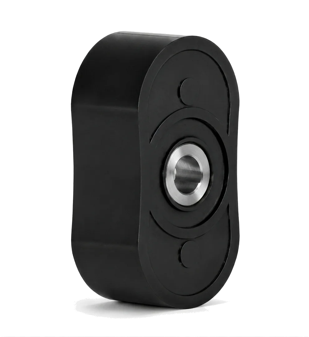
Two lobes leave larger transfer pockets between the rotor and casing. This favors the passage of large, soft or compressible solids.
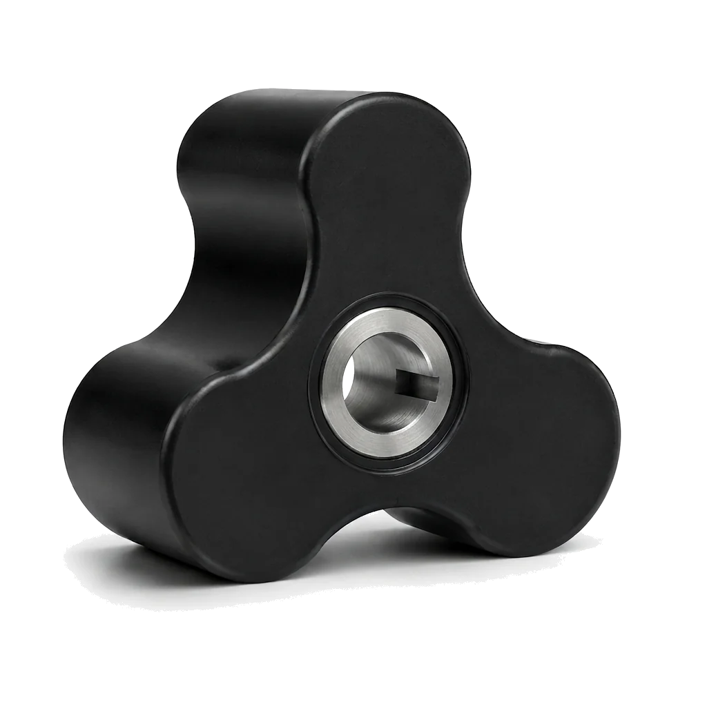
Three straight lobes divide the transfer into smaller pockets. Compared with bi-lobe, this balances solids handling with lower discharge pulsation.
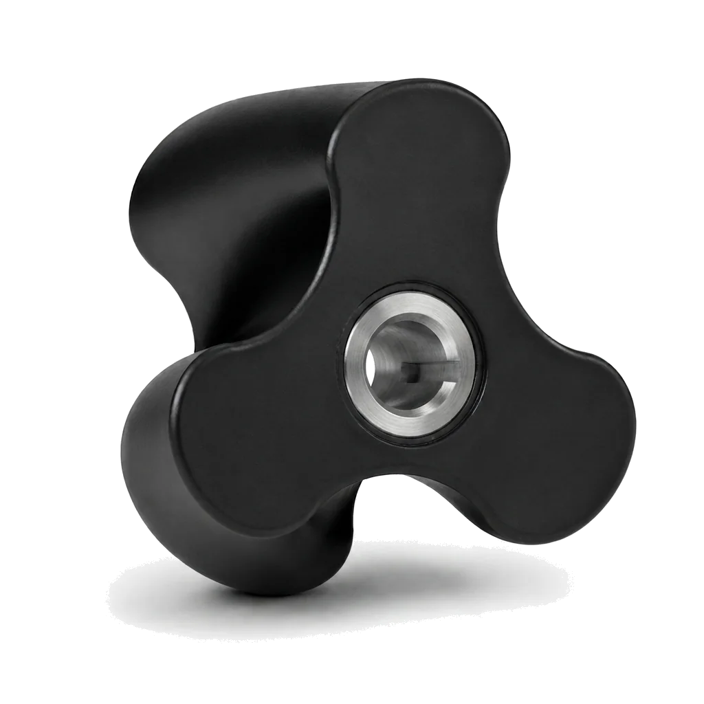
Three lobes with an axial twist engage progressively along the rotor length, smoothing displacement for Pulsation-Free transfer.
These passage figures are indicative and model-dependent. Distinguish soft or compressible solids from hard particles; diameter alone does not establish whether a solid can pass.
| Rotor Profile | Indicative Solids Passage | Discharge Pulsation |
|---|---|---|
| Bi-Lobe | Up to ~70 mm for soft or compressible solids, depending on model. Hard particles require a separate review. | High |
| Straight Tri-Lobe | Up to ~30 mm for soft solids, depending on model. Hard, incompressible particles: recommended ≤15 mm, subject to review. | Low to medium |
| Helical Tri-Lobe | Up to ~12 mm, depending on model; intended for small or no solids. | Pulsation-Free |
For coating, metal rotor, and seal compatibility, use the Materials Guide →
Share the fluid, solids, and required flow behavior. The profile, material, pump size, and operating speed are selected together.
Send solids size and hardness, viscosity, flow, pressure, and any pulsation or product-sensitivity requirements.
Review rotor coverings and metal options against process chemistry, temperature, and cleaning conditions.
Use the worksheet to organize flow, pressure, viscosity, solids, inlet conditions, and the operating cycle.