Bi-Lobe
- Indicative Solids Passage
- Up to ~70 mm for soft or compressible solids, depending on model. Review hard particles separately.
- Relative Pulsation
- High
- Typical Duties
- Thick sludge, soft chunks, high-solids organic waste.
Two synchronized rotors carry liquid around the casing from inlet to outlet. Follow the cycle, then see how rotor shape, internal slip, timing, and reverse rotation affect pump operation.
A rotary lobe pump is a positive-displacement pump. Two rotors turn in opposite directions without rotor-to-rotor contact, capturing liquid between the lobes and casing and carrying it to the outlet.
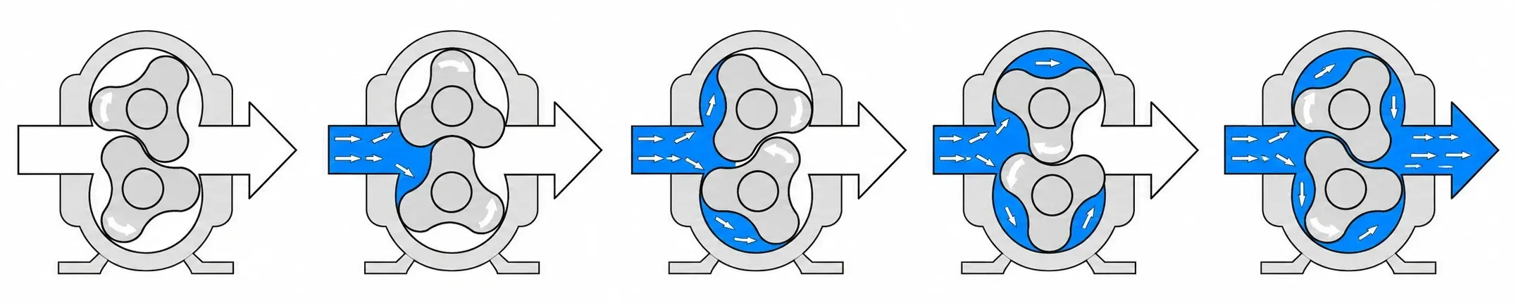
Timing gears synchronize the shafts so the rotors can pass one another without rotor-to-rotor contact.
As the rotors separate on the inlet side, the available cavity volume increases. Inlet pressure pushes liquid into the pump.
Pockets between the lobe surfaces and casing capture liquid as the rotors continue turning.
Liquid travels around the upper and lower casing paths, not through the center where the rotors intermesh.
As the lobes intermesh on the discharge side, the available cavity volume decreases and liquid is displaced into the outlet.
The liquid follows the outer casing paths rather than passing through the rotor mesh. This supports gentle transfer and soft-solids handling when rotor profile, clearances, and speed suit the fluid.
Lobe count and profile change the size of the transfer pockets and how progressively they discharge. Larger pockets favor solids passage; a helical profile spreads displacement over the rotation to reduce pulsation.
The passage figures below are indicative and model-dependent. Soft or compressible solids and hard particles must be assessed separately, including particle shape, concentration, and abrasiveness.
| Rotor Profile | Indicative Solids Passage | Relative Pulsation | Typical Duties |
|---|---|---|---|
| Bi-Lobe | Up to ~70 mm for soft or compressible solids, depending on model. Review hard particles separately. | High | Thick sludge, soft chunks, high-solids organic waste. |
| Tri-Lobe | Up to ~30 mm for soft solids, depending on model. Hard, incompressible particles: recommended ≤15 mm, subject to review. | Low to medium | Wastewater, industrial sludge, oil transfer, mixed solids. |
| Helical Tri-Lobe | Up to ~12 mm, depending on model; intended for small or no solids. | Lowest of these three profiles | Filling, polymer dosing, cosmetics, low-pulsation transfer. |
See geometry and application tradeoffs in the Rotor Profiles Guide →
Running clearances allow some liquid to leak internally from the higher-pressure discharge side back toward the inlet. This internal leakage is volumetric slip: the pump displaces a theoretical volume, but not all of it reaches the outlet.
For fully filled cavities and consistent units. Incomplete inlet filling can reduce output further; use model-specific performance data for sizing.
At otherwise comparable conditions, slip generally rises with differential pressure and falls as viscosity increases. Higher viscosity can improve volumetric efficiency, but also raises inlet losses and viscous drag — lower slip alone does not establish the final duty point.
For speed correction and startup torque, use the Viscosity Selection Guide →
The rotors do not drive each other by contact. Timing gears in the drive housing synchronize the shafts; the shaft supports, housing geometry, and specified clearances keep the rotating assembly correctly positioned.
The gear train keeps the two rotors in the correct angular relationship as they turn past one another.
Gaps must allow for temperature, rotor material, and the expected fluid. Insufficient clearance risks contact; excessive clearance increases internal leakage.
For the shaft supports and drive housing, see Structural Design →
Reversing the rotor direction reverses the pumping cycle, so the inlet and outlet exchange roles. This can support loading, unloading, and product recovery through the same pump.
The installed system must support both directions: review valve orientation, pressure-relief paths, piping, and controls. Different inlet conditions and line losses can produce different duty points in each direction.
See system arrangements and pressure protection in the Reversible Flow Guide →
Match the operating principle to the actual fluid, flow, pressure, and inlet conditions before choosing a model.
Share your fluid and operating requirements for a model and configuration review.
Use the worksheet to organize viscosity, solids, temperature, inlet conditions, and the operating cycle.
Compare rotary lobe pumps with centrifugal, progressive cavity, gear, and diaphragm alternatives.