Left → Right Transfer
If the right discharge is blocked, the relief function must release pressure from the right side to the left inlet side.
Rotary lobe pumps can reverse flow by changing the direction of rotor rotation. Review loading, unloading, and product recovery against the valve routing, pressure protection, seals, and drive controls in both directions.
A rotary lobe pump uses a largely symmetrical pumping chamber. Reversing rotor rotation swaps the inlet and discharge roles of the two ports.
The displacement principle is unchanged, but delivered flow and pressure depend on the suction conditions and resistance in each direction. Review both operating points rather than assuming identical system performance.
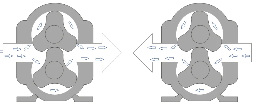
See the rotary lobe pump working principle for the displacement cycle and timing-gear function.
In terminals, chemical transfer stations, and truck-mounted systems, one reversible pump can serve both loading and unloading duties when pressure, viscosity, and suction conditions are compatible in both directions.
The same pump can transfer, recover, clean, or recirculate when the loop is piped and interlocked for both directions — without manual repiping.
Open the application guide for the fluid, installation, and operating conditions closest to your project.
A rotary lobe pump is a positive-displacement machine. If the discharge path is blocked, pressure can rise quickly. In a reversible line, which side is the high-pressure side changes when the pump reverses.
Protection must cover the discharge side in either direction. Confirm the relief arrangement, valve interlocks, and pressure instruments for the installed system; a one-way relief route does not automatically protect reverse operation.
Also review check valves, strainers, and instruments that only work in one direction — they commonly block or misread the reverse path.
If the right discharge is blocked, the relief function must release pressure from the right side to the left inlet side.
If the left discharge is blocked, the relief function must release pressure from the left side to the right inlet side.
Reversing direction changes hydraulic loading on the seals. Abrupt motor reversal can also put shock into keyways and couplings.
YANESS commonly uses field-repairable non-cartridge single mechanical seals. Review pressure direction, elastomer compatibility, and thermal exposure for the duty. Frequent reversal should use controlled ramp-down and ramp-up rather than hard electrical switching.
Check rotor keyways and coupling keys for correct fit. Confirm the deceleration, stop, and reverse-start sequence with the drive supplier; a soft starter alone does not establish a reversing control sequence.
Review seal-face materials and elastomer compatibility for the fluid, temperature, and cleaning conditions in each transfer direction.
If reversal coincides with tank emptying or air exposure, also review Dry-Run Capability.
Request pump sizing, prepare the two-way duty data, or review reversal troubleshooting.
Share loading and unloading rates, suction lift, pressure limits, valve sequence, and expected reversal frequency.
Use the selection guide to organize viscosity, solids, pressure, suction condition, runtime, and motor-control assumptions.
Pressure spikes, cavitation, wrong valve position, vibration, or wrong flow direction — diagnose before restarting.