Select an illustration to view the original image.
1. Rotary Lobe Pump Structure Overview
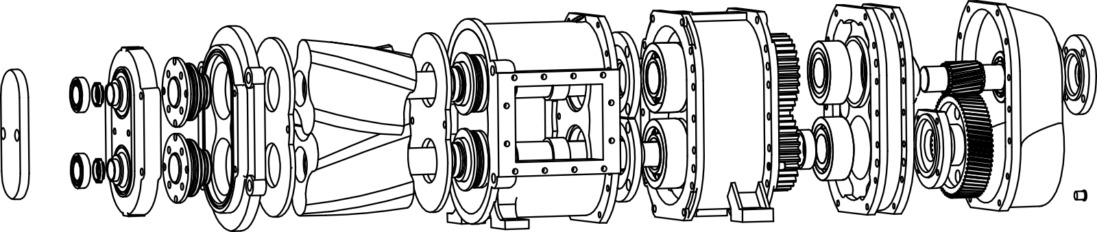
The platform uses a modular layout: gearbox, timing gears, shafts, wet-end casing, rotors, mechanical seals, isolation chamber, and front-cover service access for field work.
Packages may use optional built-in reduction for compact speed reduction, or a direct-shaft layout for project-specific drives — exact length still depends on model and motor.
2. Piping, Installation & Shaft Alignment
Mount the full pump package horizontally on a rigid, anchored steel baseplate. The driver, coupling, guard, and pump should be aligned before operation.
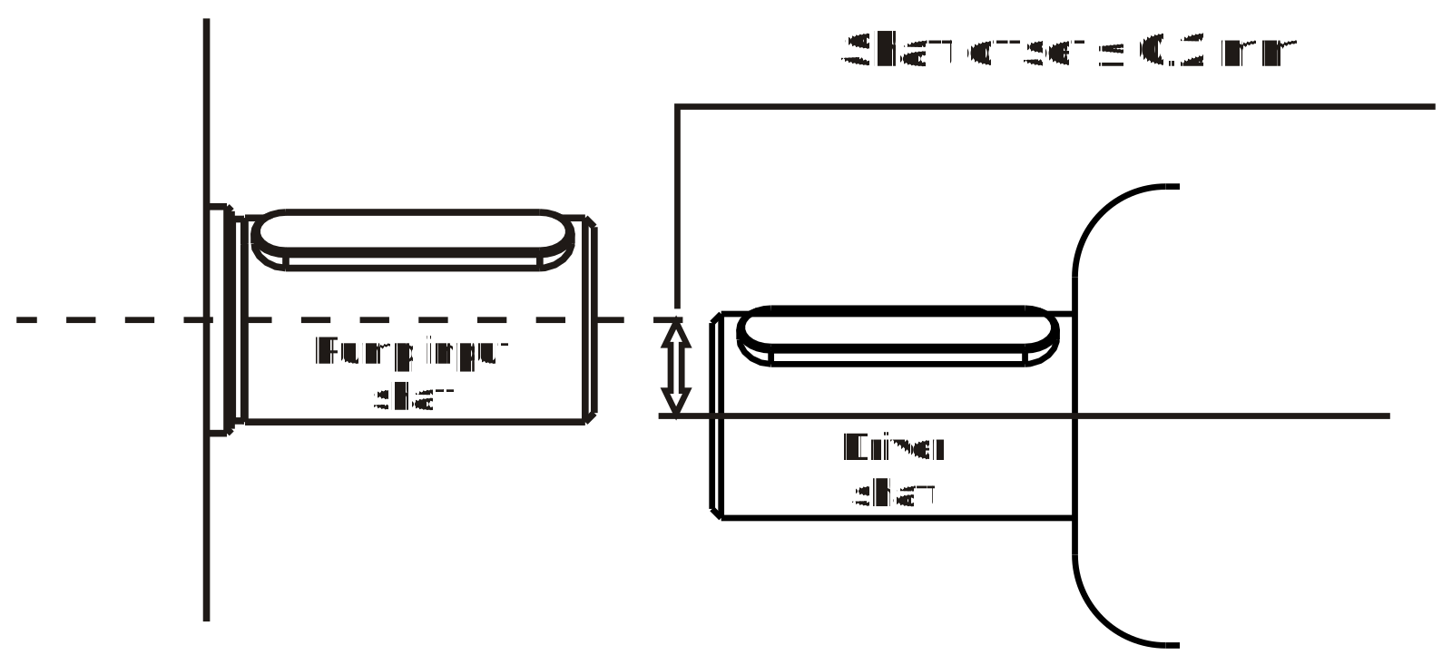
For flexible-coupling drive packages, verify pump shaft and driver shaft coaxial alignment before startup. Keep coupling alignment deviation within 0.2 mm unless the project drawing specifies a tighter tolerance.
Reserve no less than 600 mm x 600 mm around the front and service side for cover removal, rotor pulling, liner replacement, and seal inspection.
Self-priming can be reviewed by duty, but high suction lift, hot liquid, or gas entrainment can still cause vapor lock or cavitation. Keep suction lines short, sealed, and generously sized.
3. Oil Maintenance & Safe Lubrication Specifications
Lubrication is separated between the gear drive chamber and the mechanical seal isolation chamber to reduce contamination risk.
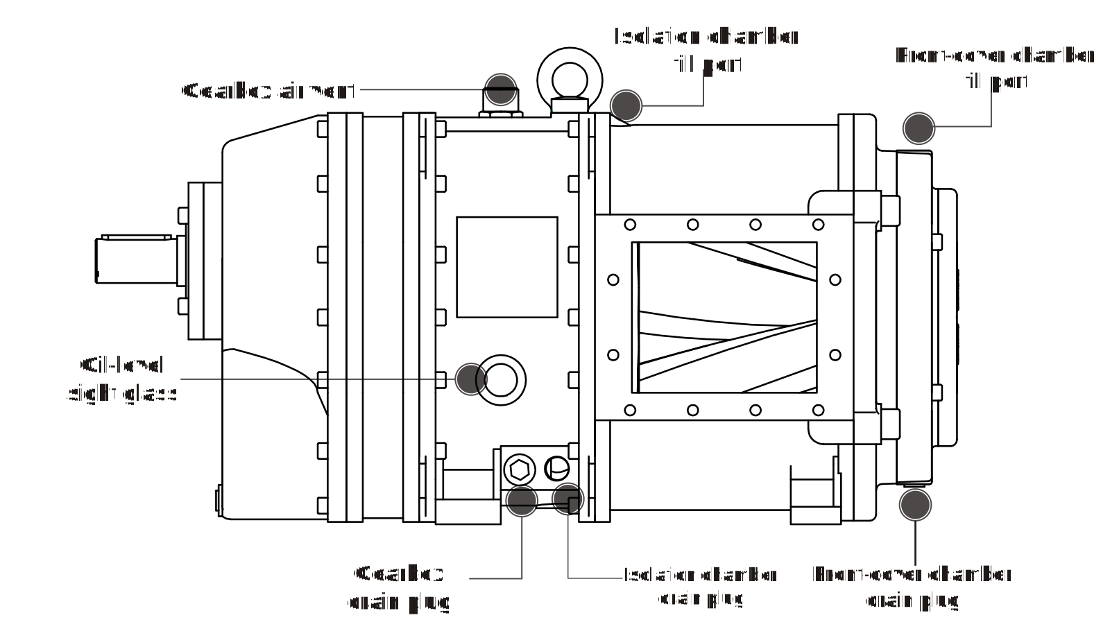
Check oil level through sight glasses before startup and after service. Do not mix contaminated oil from seal leakage with gearbox lubricant.
| Location | Inspection Point | Recommended Oil / Action |
|---|---|---|
| Gearbox / timing gear chamber | Oil level, color, temperature, gear noise | Use ISO VG 220 EP enclosed gear oil (ISO 6743-6, CKD) unless the project data sheet specifies otherwise. Top up or replace oil if depleted, overheated, or contaminated. |
| Intermediate isolation chamber | Oil level and leakage indication | Use 15W-40 diesel engine oil unless the project data sheet specifies otherwise. Maintain oil level and inspect seals if media appears at indicator drains. |
| Cover chamber and drain routes | Drain, injection, and indicator holes | Keep the injection hole (indicator drain) open and clean. Seal the bottom drain hole after oil fill — only the indicator drain should stay open. |
4. Startup & Operation Checklists
Verify these items before startup to reduce dry starting, cavitation, binding, and pressure-spike risk.
- ✓Confirm gearbox and isolation chamber oil levels.
- ✓Verify all pipe flanges and casing connections are sealed.
- ✓Check flange and connection tightness for leakage before loading the pump.
- ✓Confirm all accessories are installed correctly, including guards, flushing or cleaning devices, and coupling protection.
- ✓Manually rotate the coupling to check for rotor binding or abnormal noise.
- ✓Confirm motor rotation direction matches the intended suction and discharge pipeline.
- ✓Open both inlet and outlet valves completely before starting.
- ✗Do not run the pump against closed valves.
- ✗Avoid long unattended dry running after startup, especially where flexible hoses or temporary suction lines are connected.
- ✗Do not force the coupling if manual rotation meets persistent resistance — review clearances instead.
5. Wet-End Rebuild
Wet-end service can often be done in place when the pump is isolated, cleaned, depressurized, and locked out — access still depends on pipe clearance and site procedure.
Rebuild follows a fixed sequence — each stage depends on the previous one:
- Front Cover Removal — isolate, depressurise, and remove the cover to expose the rotor chamber.
- Rotor Extraction — remove hardware from the shaft, then pull both rotors using the dedicated puller tool.
- Seal & Liner Service — disassemble mechanical seals, replace wear liners if fitted, and adjust rotor axial tightness before reassembly.
5.1 Front Cover Removal
Before removing the front cover, ensure the pump is fully isolated and all residual pressure is released. Fluid inside the pump casing may spray out under pressure — use a shield or barrier cloth around the cover before loosening bolts.
- 1Turn off power or disconnect the driver.
- 2Close both inlet and outlet valves completely.
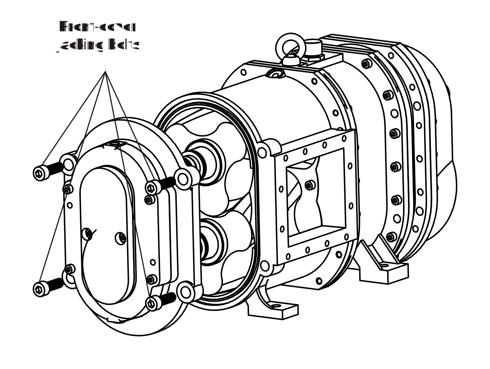
- 3Loosen all cover bolts halfway, then use the jacking screws to push the cover clear of the casing. Allow all residual fluid to drain before fully removing the bolts.
- 4Once the casing is empty, remove the cover bolts fully and lift the cover away.
- ⚠Fluid inside the pump may spray under pressure. Always use a shield or barrier cloth to cover the cover face before loosening bolts.
5.2 Rotor Extraction
With the front cover removed, follow these steps to extract the rotors in sequence. Lubricate the shaft before reinstallation. Install in the reverse order.
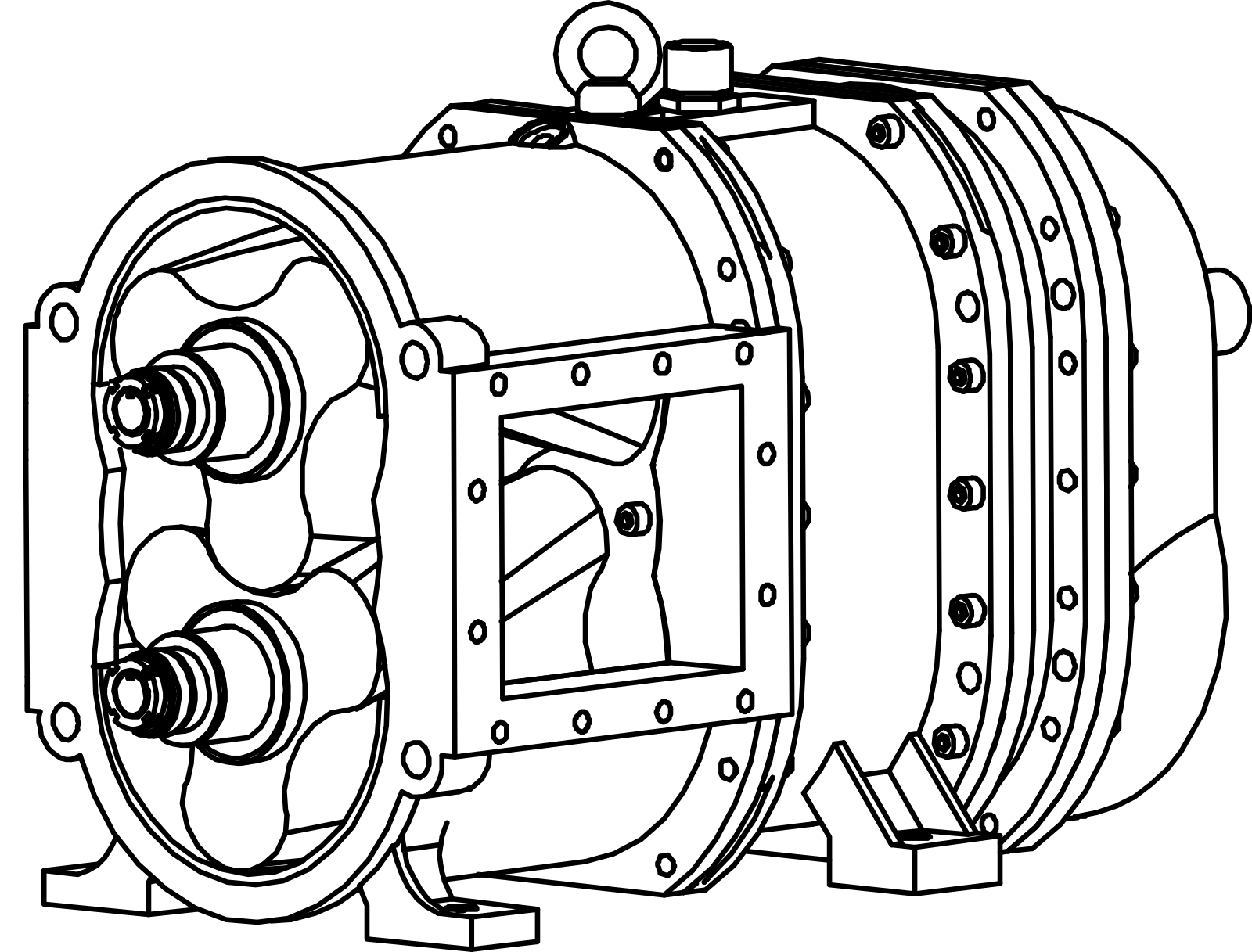
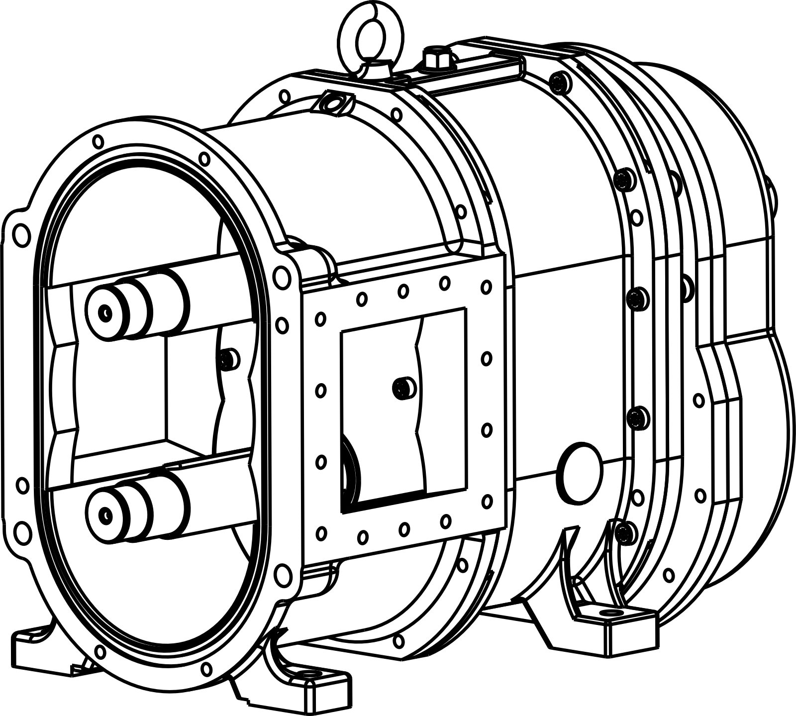
Cover Removed — Rotor Chamber Exposed
Confirm power is cut, drive is locked out, and both valves are closed. Inspect all removed parts for damage before proceeding.
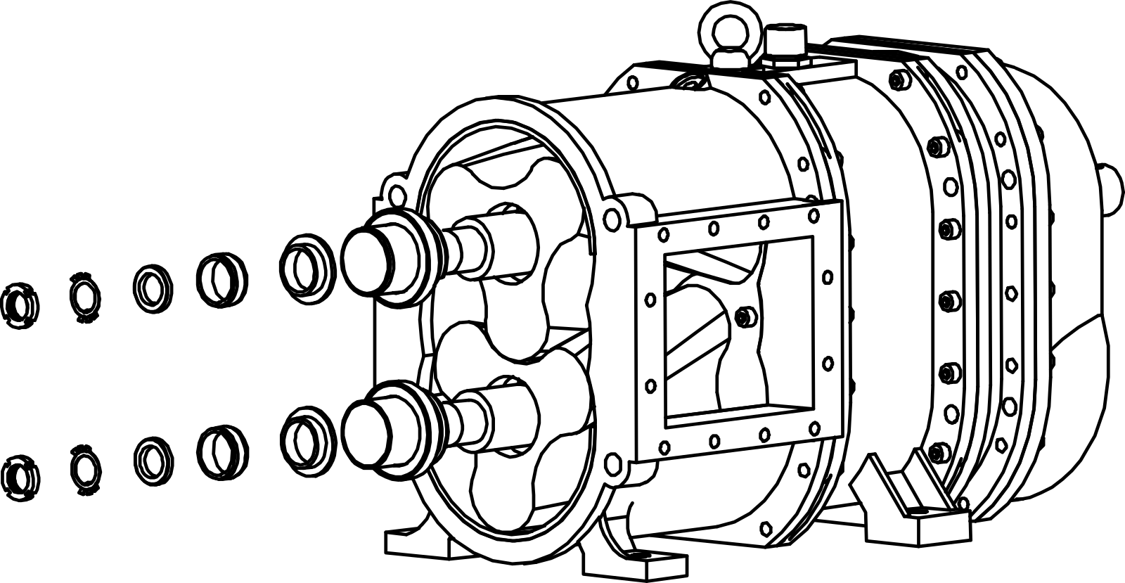
Remove Locknut, Tab Washer, Oil Seal Sleeve & Dynamic Seat
Remove the round locknut, tab washer, oil seal sleeve, and dynamic seal seat from the shaft in sequence. Keep parts organised for inspection.
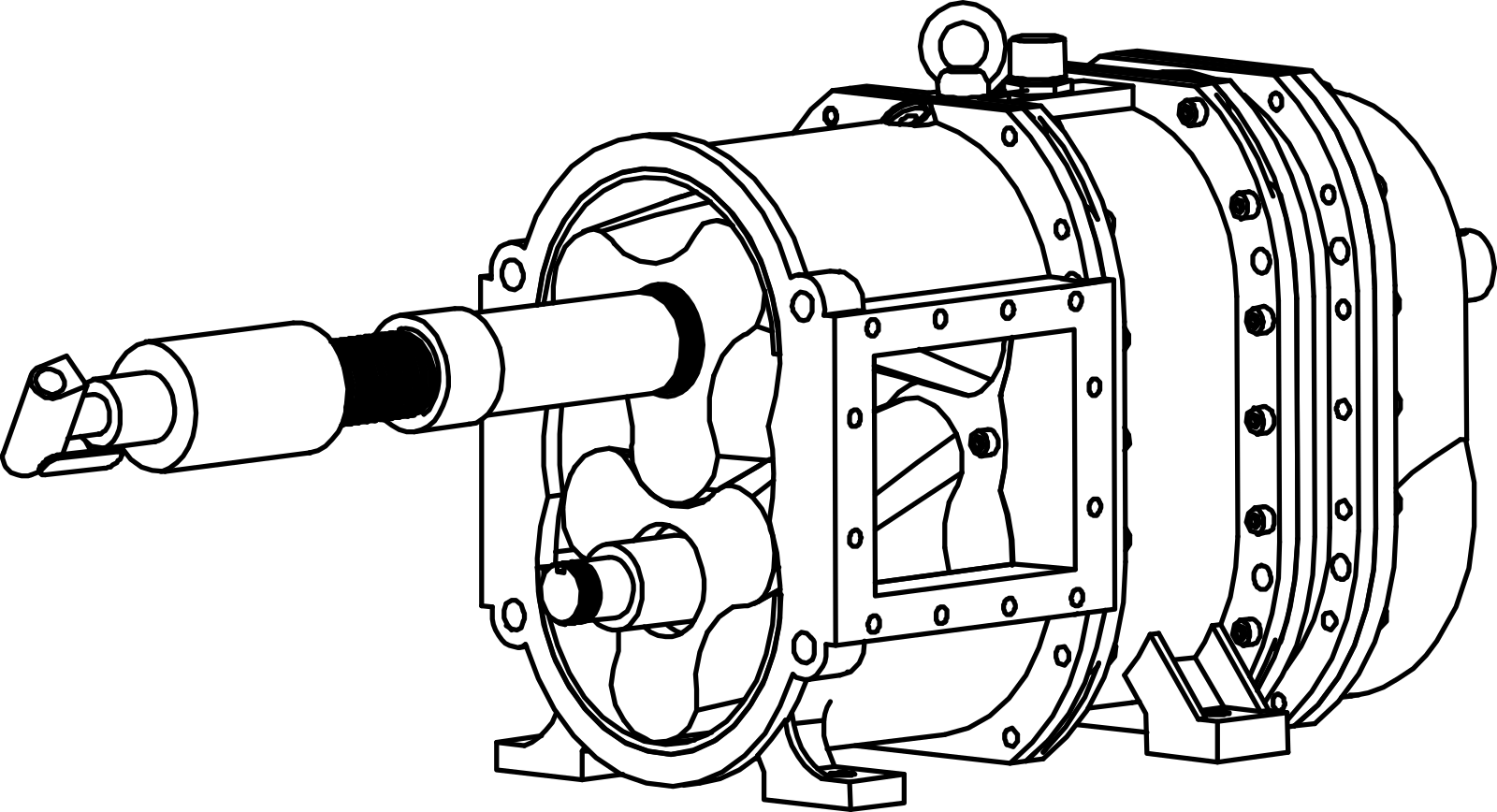
Connect Hydraulic Puller to Dedicated Tool
Attach the hydraulic ram to the dedicated YANESS rotor puller tool and thread it firmly into the rotor central threaded hole.
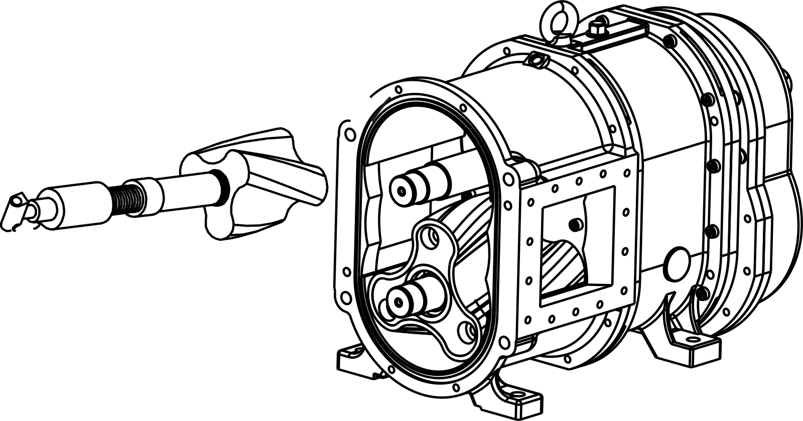
Pull Top Rotor Out
Operate the puller tool slowly to slide the top rotor off the shaft splines. Do not hammer the rotor faces or shaft ends.
Repeat for Bottom Rotor
Apply the same method to extract the bottom rotor. Clean the empty casing and inspect the wear liners for scoring or thinning before reassembly.
5.3 Mechanical Seal Disassembly
After opening the pump cover, the mechanical seal splits into two assemblies: the static ring assembly seated in the cover, and the dynamic ring assembly on the rotor shaft. The disassembly procedure covers external seals (accessible after cover removal) and internal seals (requiring rotor extraction first).
Note: the external mechanical seal configuration shown here applies to dual-bearing support pumps only. Single-bearing configurations use a different seal arrangement — refer to the pump specification before proceeding.
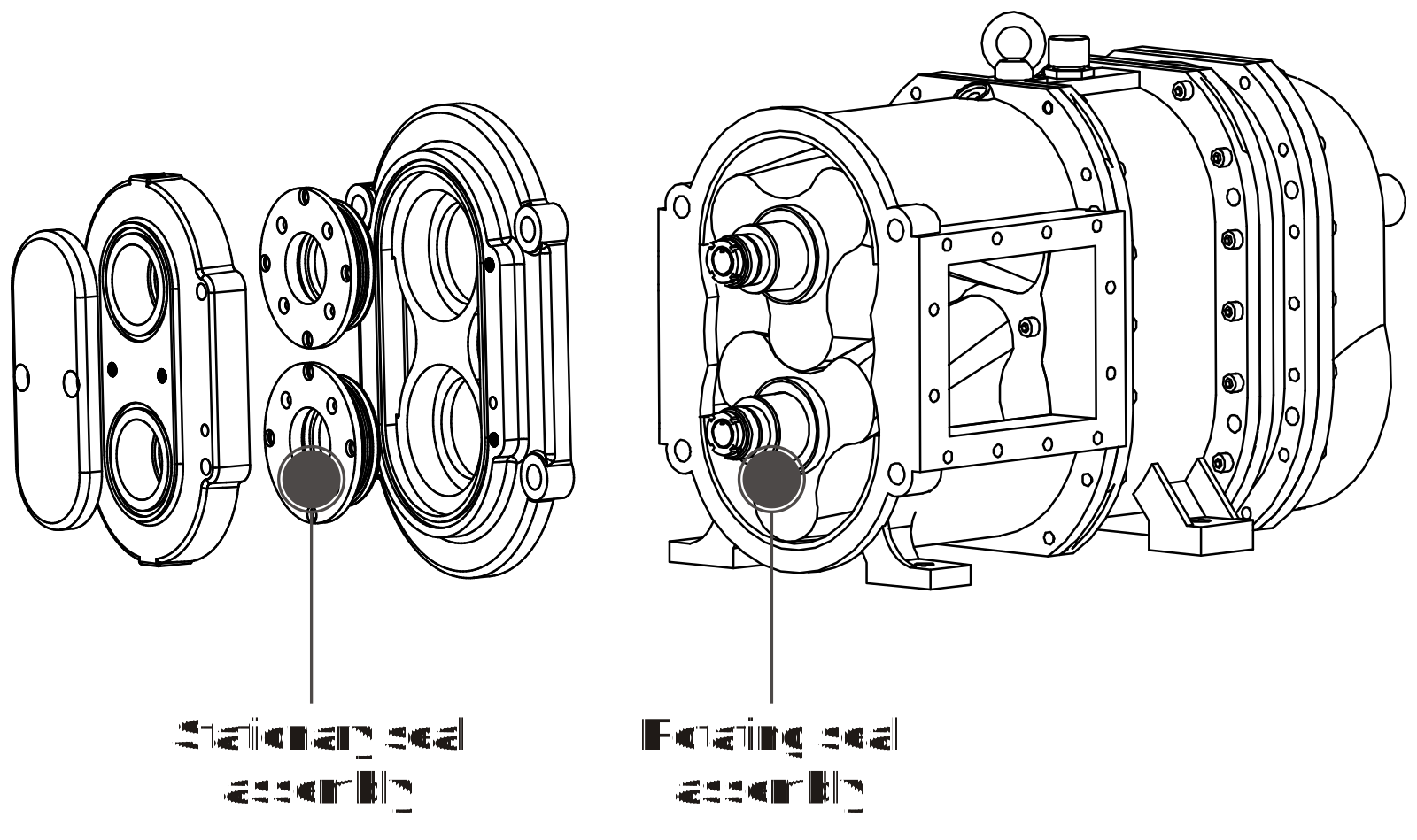
Static & Dynamic Ring Assemblies
This is the external mechanical seal configuration, found on dual-bearing support pumps. With the cover open, the static ring assembly is seated in the pump cover. The dynamic ring assembly is mounted on the rotor shaft. Check seal faces and O-rings for wear or damage before deciding whether to replace.
Internal Seal Disassembly — Requires Rotor Removal First
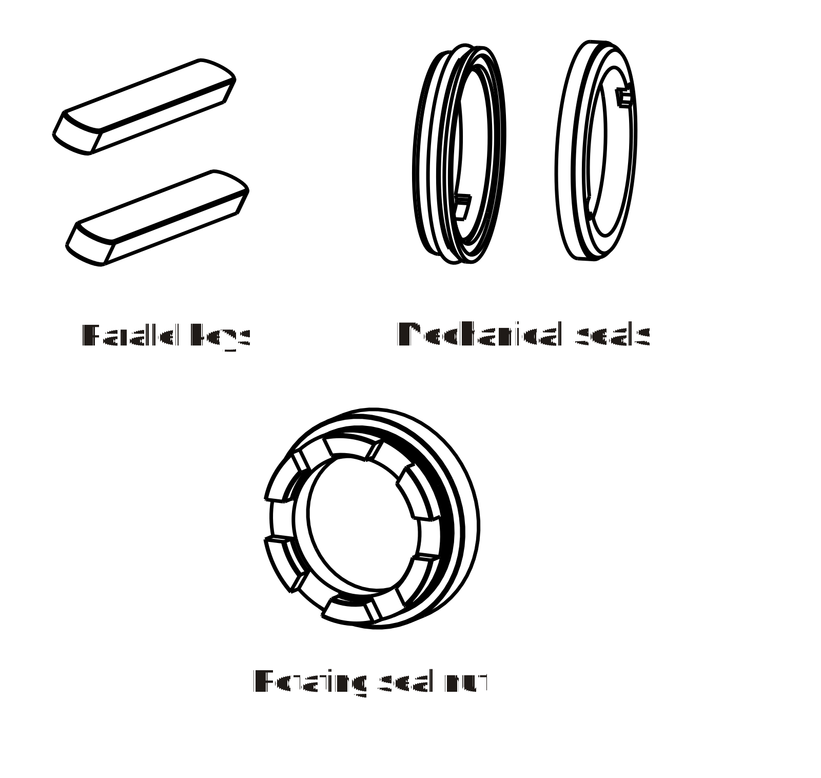
Internal Seal Component Overview
The internal seal disassembly covers: parallel keys, mechanical seal faces, and the dynamic ring locknut. Inspect each part for scoring, swelling, or thermal damage.
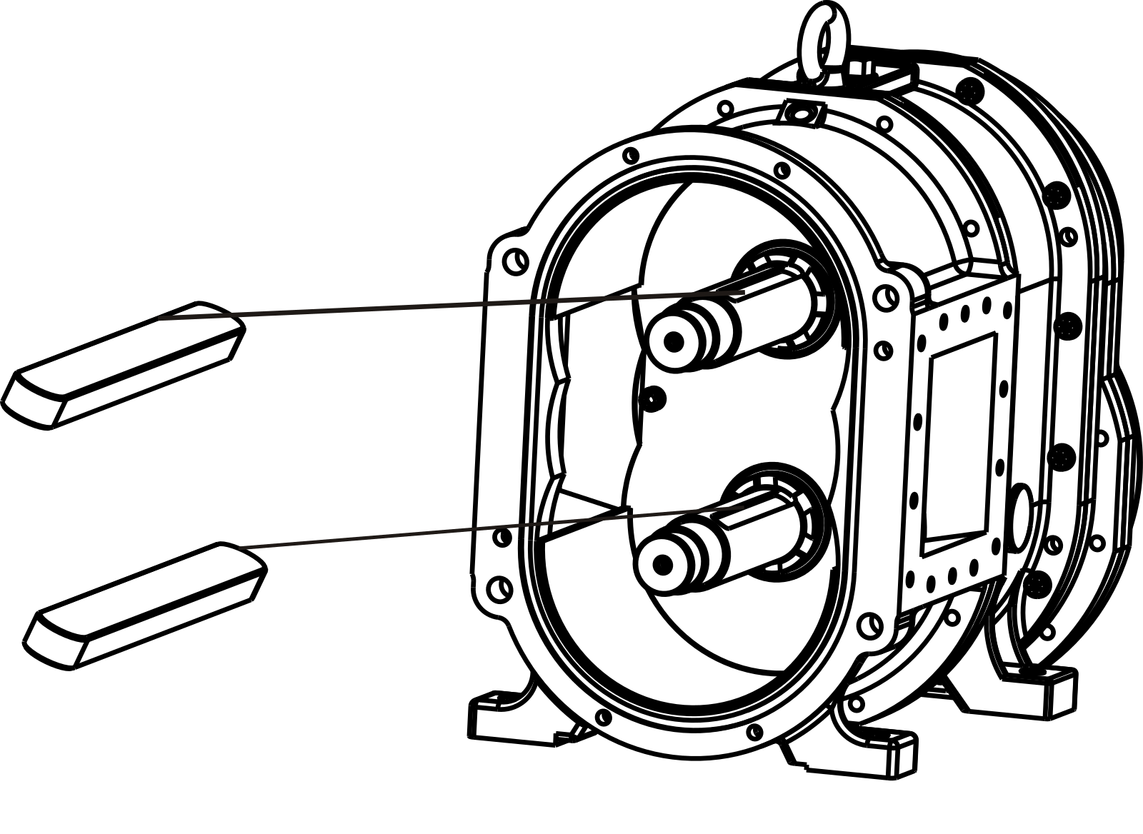
Remove Two Parallel Keys
Slide the two parallel flat keys out of the shaft keyslots. This prevents sharp keyway edges from scoring the seal O-rings during extraction.
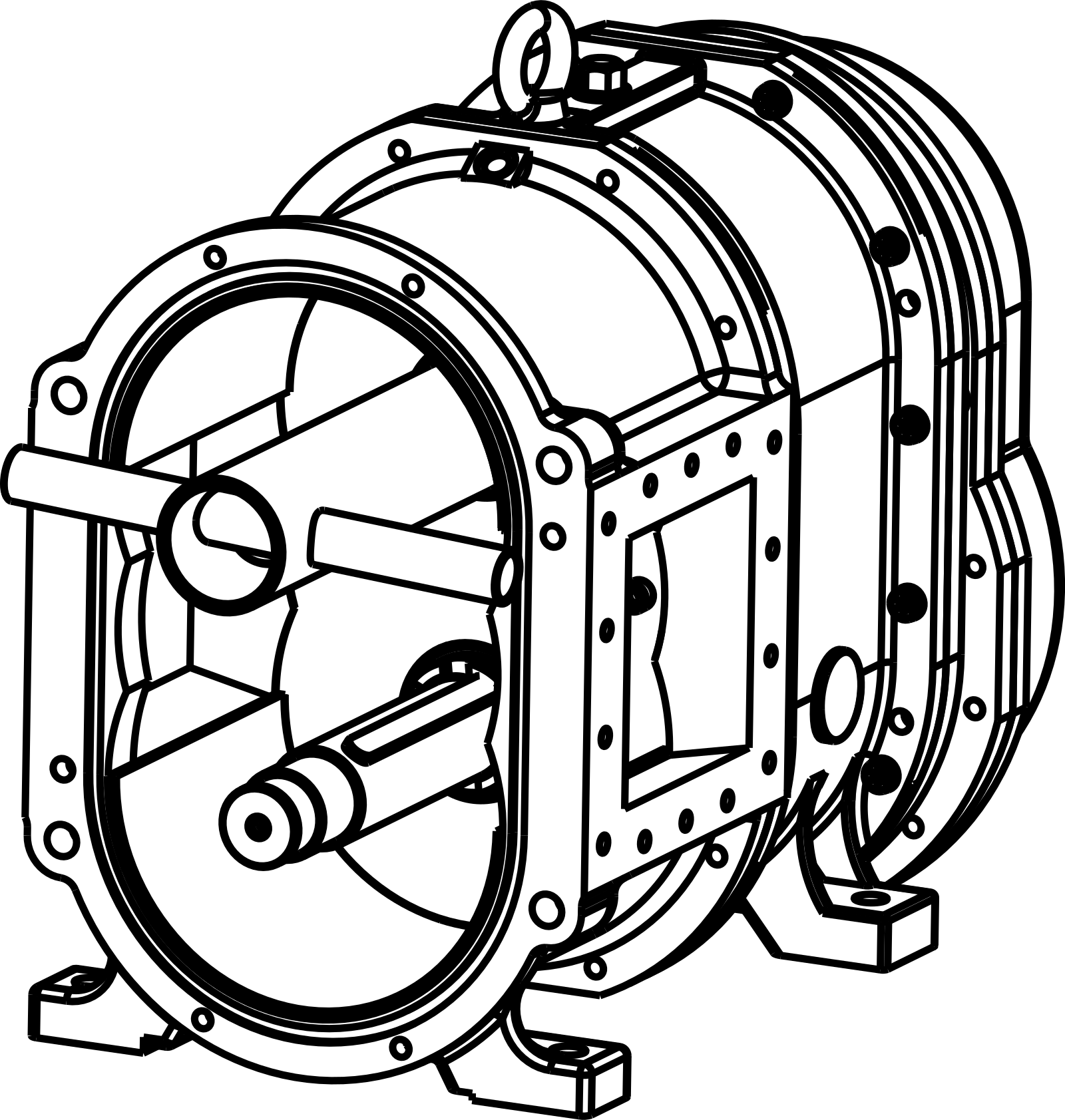
Insert T-Tool & Align with Locknut
Insert the YANESS dedicated T-tool into the pump casing. Align the tool's locating pins precisely with the slots on the dynamic seal locknut.
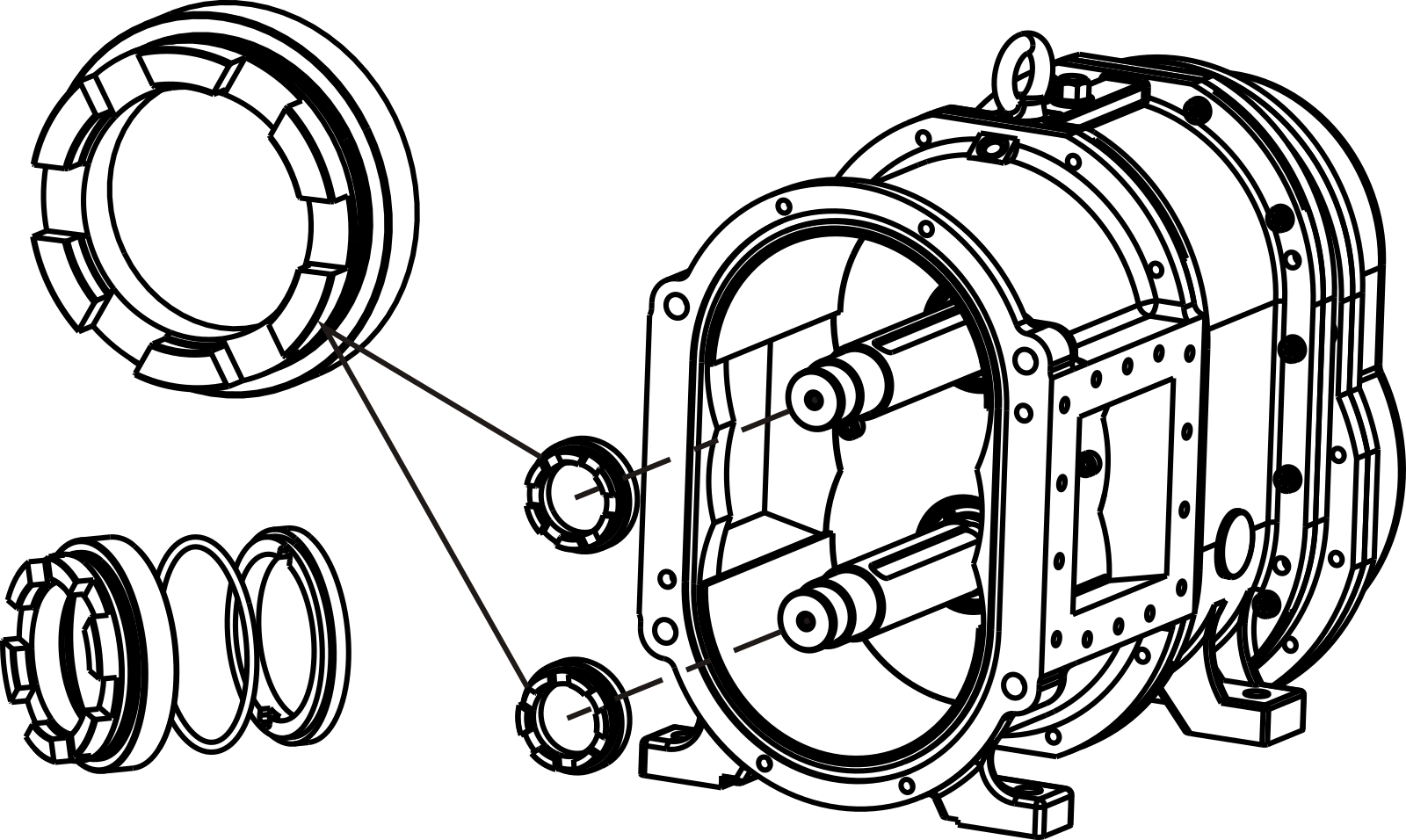
Extract Dynamic Ring Assembly
Use the T-tool to unscrew the locknut counter-clockwise. Slide the dynamic ring, spring, and elastomer smoothly off the shaft.
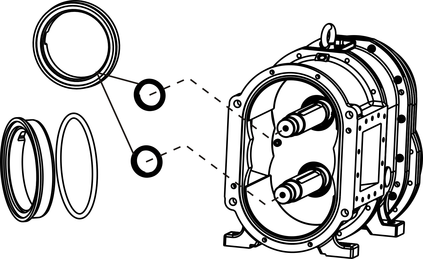
Extract Static Ring Assembly
Carefully pull the static ring and its O-ring from the housing seat. Clean any build-up from the casing seat before fitting new components.
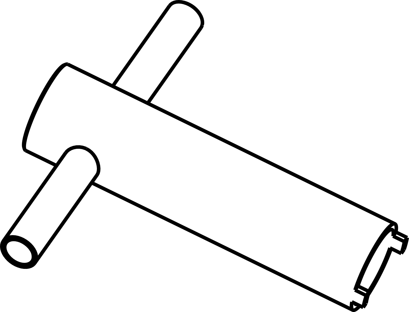
Dedicated T-Tool
The YANESS dedicated T-tool is recommended for internal seal disassembly — it engages the locknut slots precisely and reduces the risk of damaging the seal faces or shaft during removal.
5.4 Wear Liner & Axial Plate Service
Severe liner wear reduces delivered flow and raises slip. Where fitted, YANESS packages use two liner types: axial wear plates (inner and outer) and radial liners (upper and lower).
Liners are an optional wear-protection feature — not standard on all configurations. Check the pump specification before ordering replacement parts.
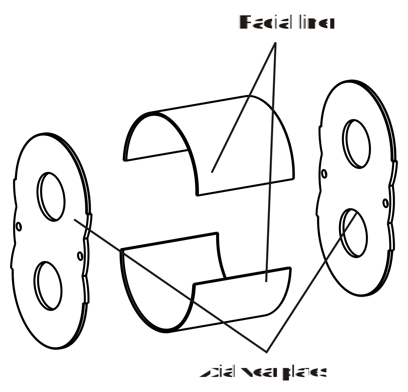
Radial & Axial Liner Positions
Radial liners protect the upper and lower casing bore. Axial wear plates protect the inner gear-side wall and the pump cover face. Inspect both directions separately after rotor removal.
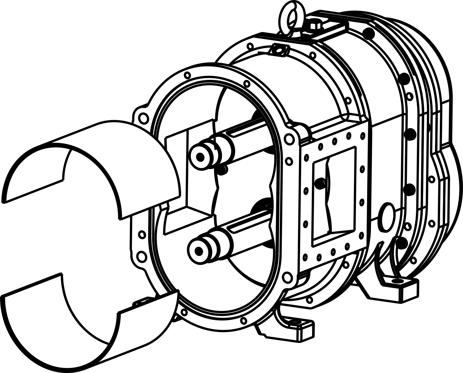
Remove Radial Liners
With rotors extracted, remove the two radial liner panels from the upper and lower casing bore. Check for scoring, grooving, or thinning caused by sand or abrasive solids.
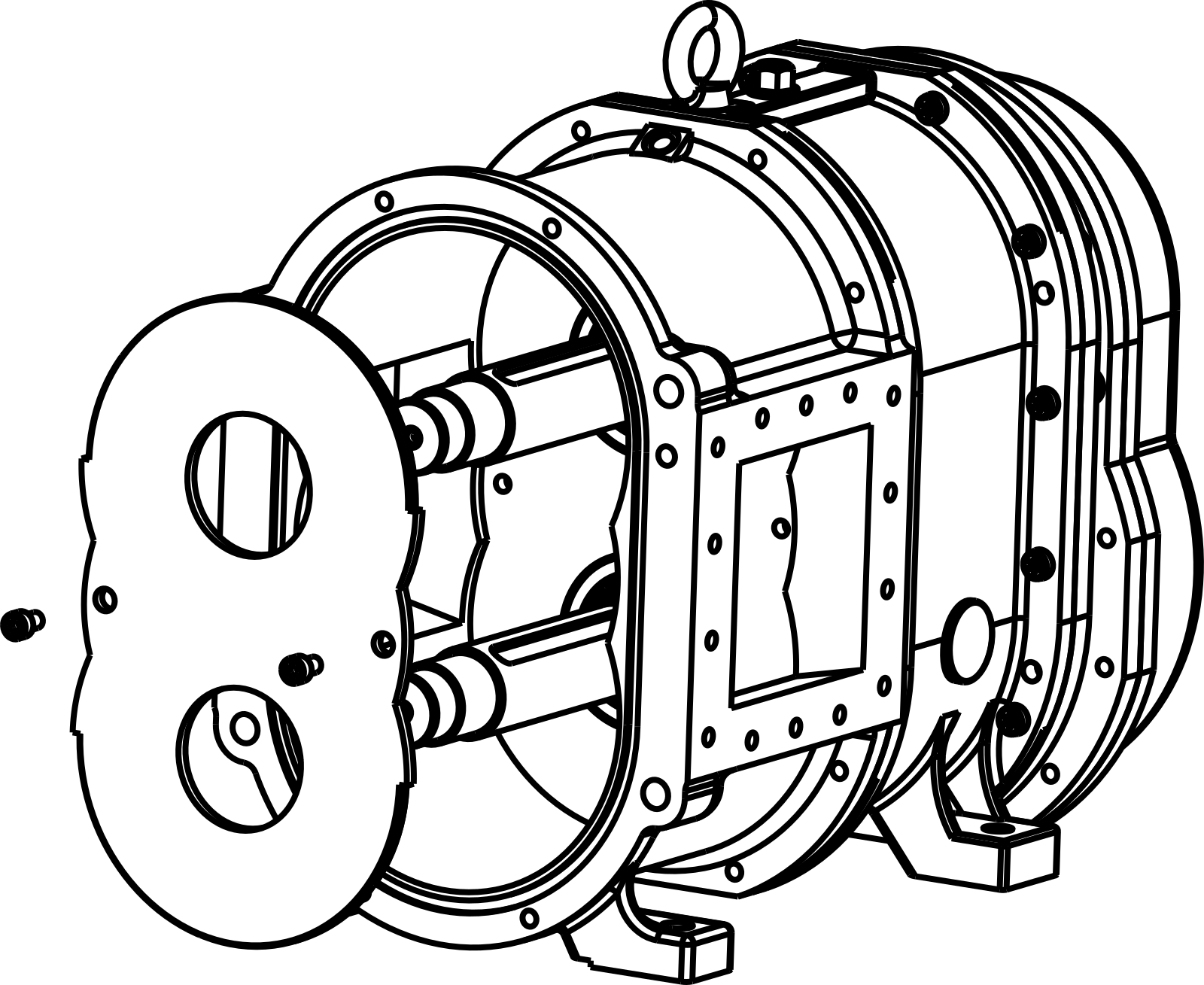
Remove Inner Axial Wear Plate
Remove the inner axial wear plate from the gear-side wall. Lay out all removed liner components for inspection before ordering replacements.
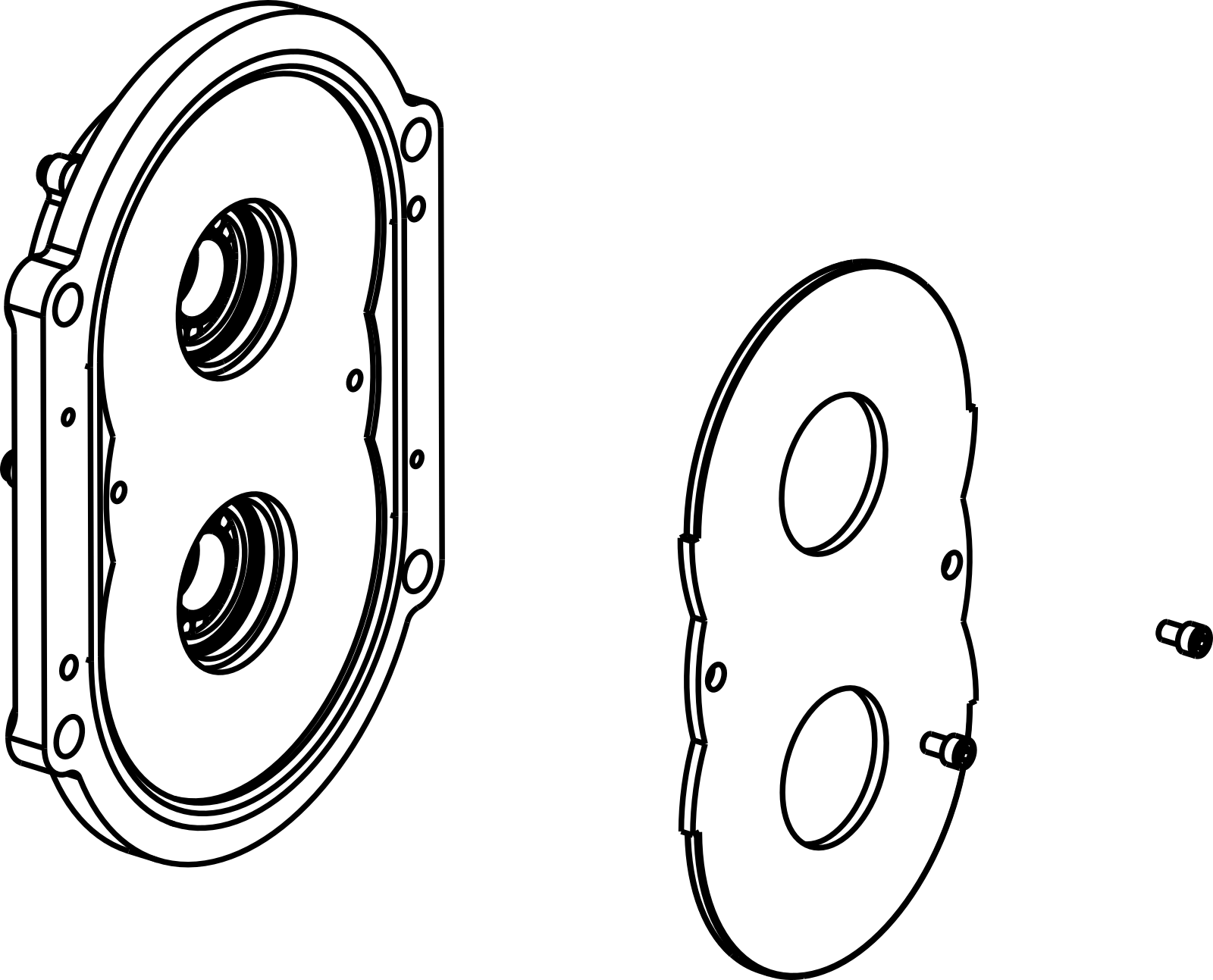
Remove Axial Wear Plate from Cover
Remove the axial wear plate from the pump cover. Inspect the cover seat surface before fitting the new plate. Install all liners in reverse order and confirm flush seating before reinstalling rotors.
5.5 Rotor Axial Tightness & Seal Nut Adjustment
To adjust rotor axial tightness, the rotors must first be removed. Rotate the mechanical seal nut in the indicated direction, 1/6 of a turn at a time, until the keyway slot aligns with the seal nut opening. Do not over-tighten or back out beyond one slot.
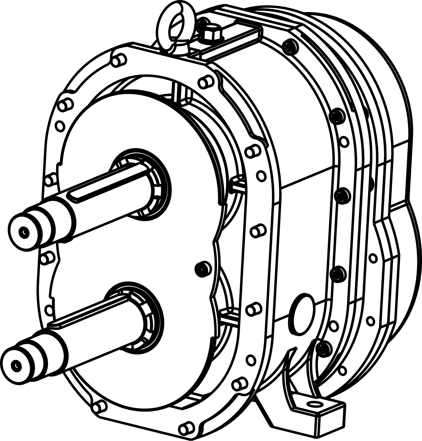
Remove Both Rotors
Axial tightness adjustment requires rotor removal first. The pump casing is shown without casing shell for illustration — casing removal is not required in practice.
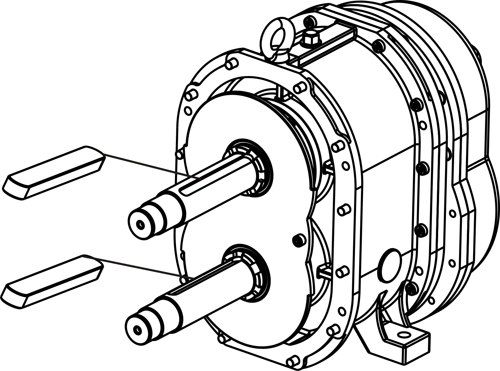
Remove Two Parallel Keys
Remove the two parallel keys from the shaft keyslots to allow the seal nut to rotate freely during adjustment.
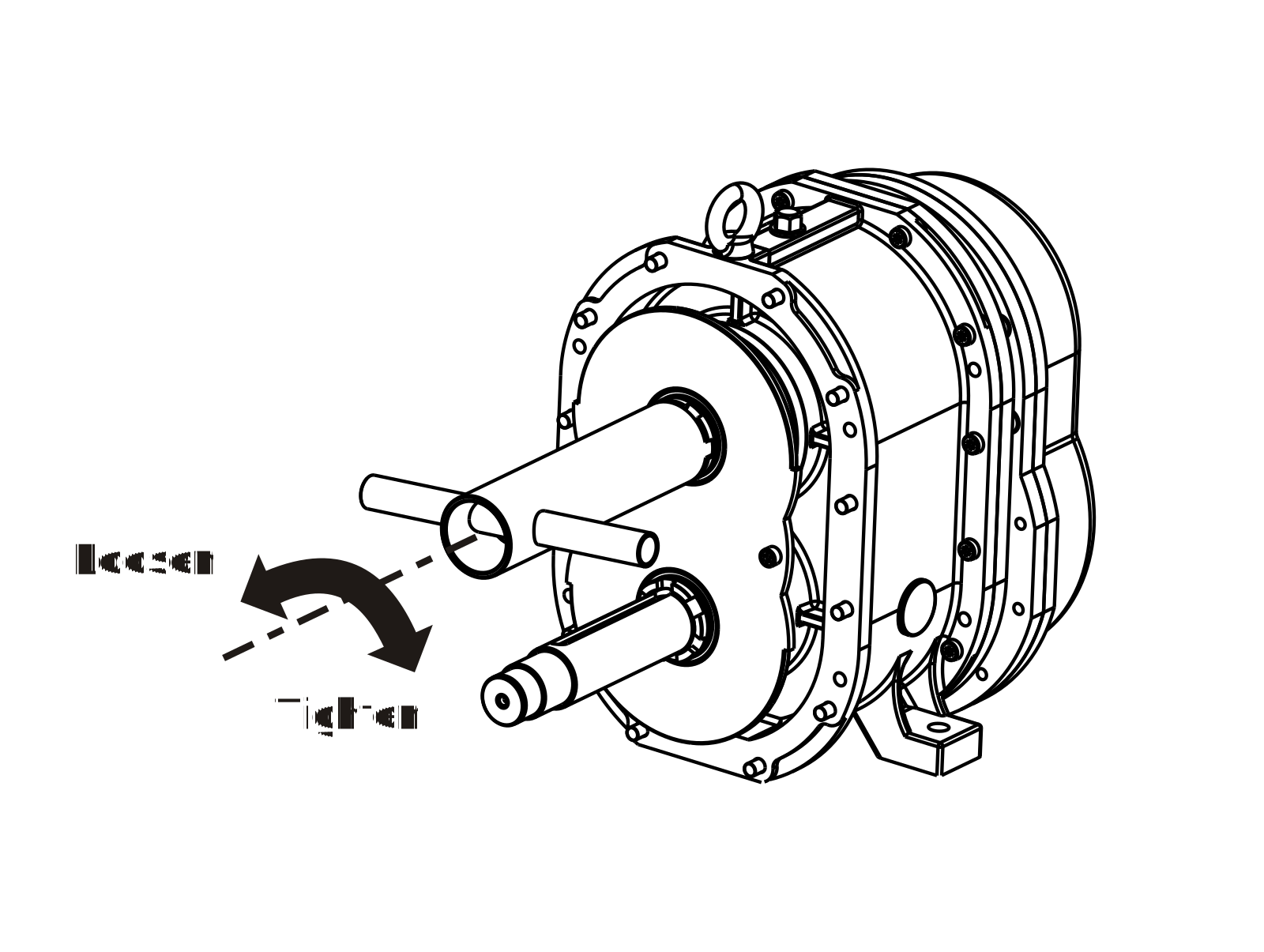
Rotate Seal Nut in 1/6-Turn Increments
Rotate the mechanical seal nut in the direction shown, 1/6 of a turn at a time, until the keyway slot aligns with the seal nut opening. Do not over-tighten or back out beyond one slot.
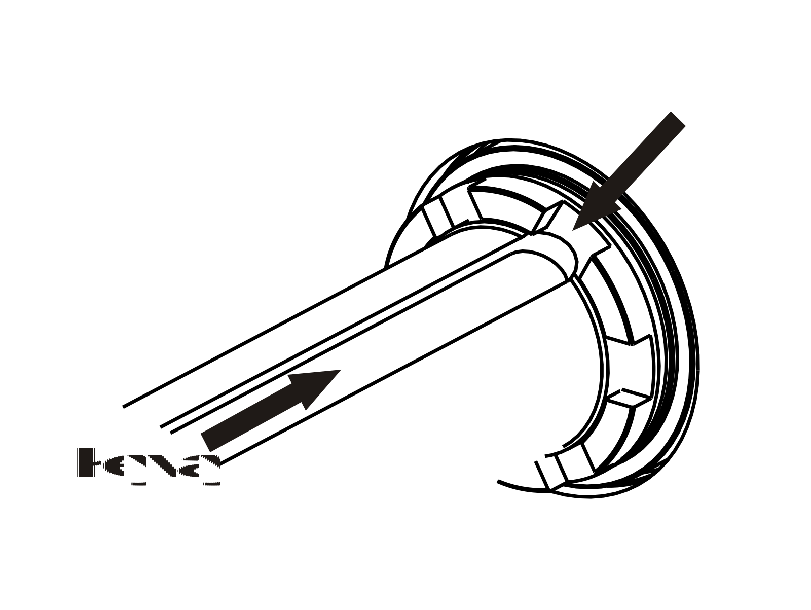
Use Dedicated Seal Tool to Adjust
Insert the dedicated mechanical seal tool and turn in the indicated direction (loosen or tighten) until the keyway and nut opening align. Insert the key to lock.
5.6 Wet-End Rebuild — Video Manual
The video walks through wet-end rebuild as a continuous reference alongside the written steps: cover removal, rotor extraction, seal disassembly, liner service, and axial adjustment.