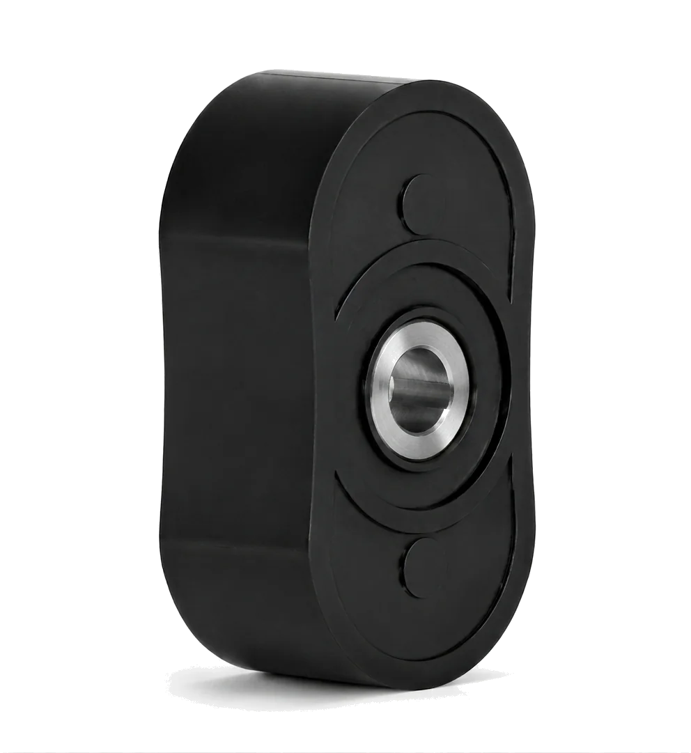
Bi-Lobe: Maximum Solid Clearance
Bi-lobe rotary pump geometry provides maximum internal pocket clearances for large gravel, fibers, soft solid chunks, and thick primary sewage sludge.
Explore optional reduction gears, the isolation chamber, shaft support, and rotor profiles. See how these components affect installation space, seal protection, and application fit.
YANESS offers an optional factory-fitted speed-reduction gear set inside the pump drive housing. It lets a standard-speed motor drive the rotors at the lower speed required by the duty, without a separate external reducer or geared motor.
This arrangement can shorten the package and reduce alignment work associated with an external reducer. A standard-speed motor generally has a lower purchase cost than a geared motor.
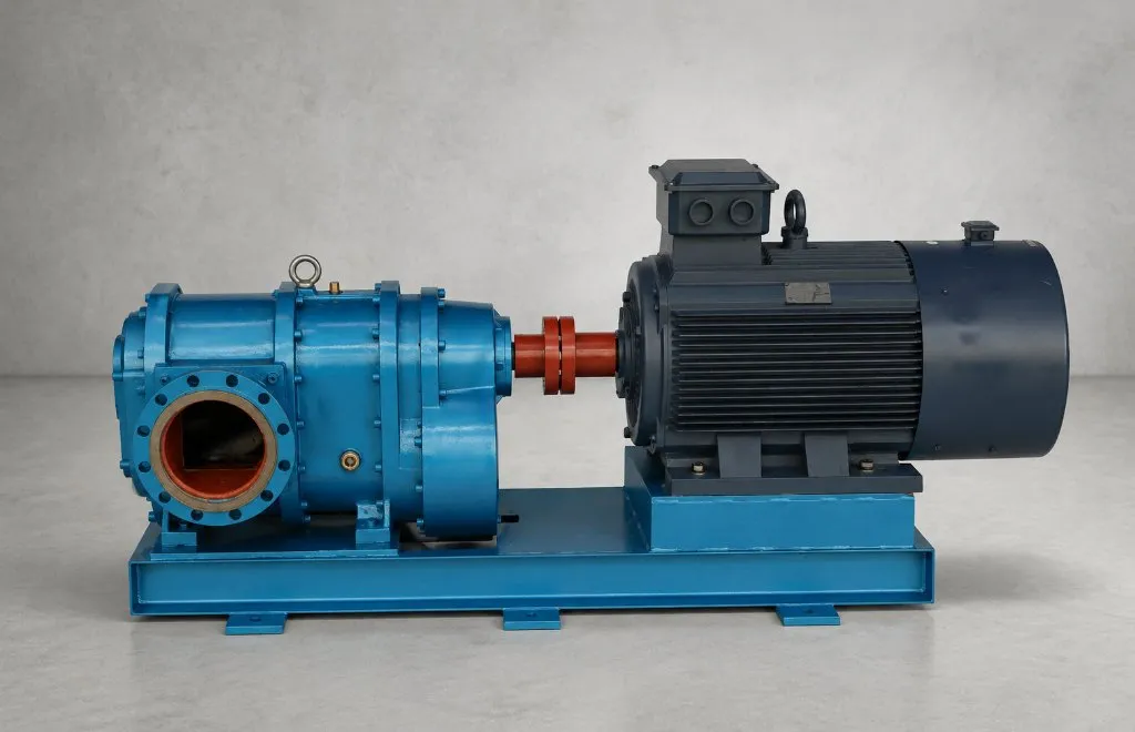
For the displacement cycle and the role of timing gears, see the rotary lobe pump working principle.
YANESS places a dedicated oil-filled intermediate isolation chamber between the wet end and the dry gearbox. The barrier fluid helps cool and lubricate the seals, and gives leakage a visible path through indicator ports before process media reaches the gear oil.
Contains the process medium being pumped.
Oil-filled chamber supporting seal cooling and lubrication.
Leakage indicator port: visible detection if the process seal leaks.
Gears and bearings run in gear oil, separate from the process medium.
For operating limits and monitoring around seal lubrication, review dry-run capability and protection.
Under high viscosity or higher differential pressure, rotors see heavy radial loads. Double-support is the YANESS default: bearings on both sides of the rotors help hold alignment, reduce shaft deflection, and protect seal and bearing life on abrasive or high-pressure duties. The front support is integrated into the pump cover, keeping the arrangement compact. Single-support remains available for duties that prioritise a simpler structure.
YANESS rotary lobe pumps are not limited to one rotor configuration. Rotor lobe geometry can be reviewed around solids size, pulsation tolerance, viscosity, abrasion, cleaning method, and target flow behavior.
Bi-lobe rotary pump geometry provides maximum internal pocket clearances for large gravel, fibers, soft solid chunks, and thick primary sewage sludge.
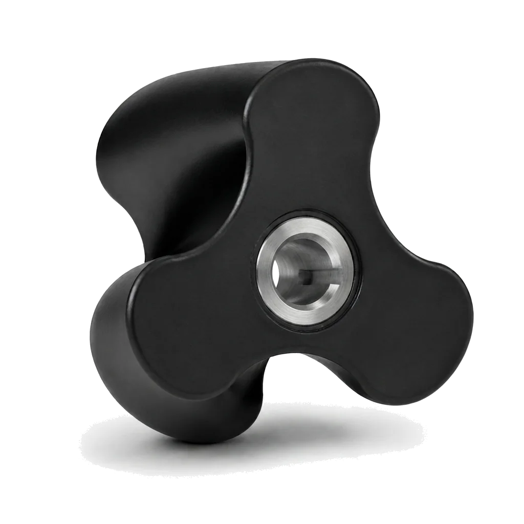
Helical tri-lobe geometry uses three twisted lobes to smooth continuous flow in dosing, filling, polymer transfer, and other shear-sensitive duties.
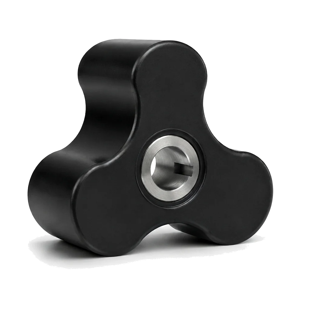
Tri-lobe standard geometry balances self-priming behavior, solids passage, and moderate pulsation control for oil sweeps and general sludge.
Compare rotor types and design tradeoffs, then check wetted materials and elastomer compatibility for the fluid and cleaning conditions.
Next is usually dimensional drawings for installation fit, or a duty review for torque, speed, and shaft-support selection.
Download the brochure for standard model dimensions. Request STEP, DWG, or package layout drawings for your project configuration.
Send fluid, flow, pressure, and site limits. YANESS reviews torque, speed ratio, and shaft-support fit before recommending a model.