Yes, provided the machine is configured and approved for hydraulic motor duty. Water passes from higher to lower pressure and turns the rotors; the shaft then drives a generator. The energy comes from the water supply, not from the pump itself.
The practical question is how much pressure you can recover while still delivering the flow and pressure the downstream process needs. A gravity-fed supply may have head to spare. A pumped circuit needs a different calculation because you must count the electricity used to create that pressure.
| Situation | What to establish |
|---|---|
| Gravity-fed water supply | Available head and flow through the year, after pipe losses and the downstream pressure requirement. |
| Existing pressure-reduction point | The pressure that can be recovered without compromising water delivery, process control, or supply continuity. |
| Pumped process or test circuit | The net energy balance: recovery can reduce losses, but does not turn the circuit into a source of surplus energy. |
Assess the machine in generating duty. Reversible liquid transfer and hydraulic power generation are different operating requirements.
1. How Much Pressure Can You Recover?
In a gravity-fed system, elevation supplies the hydraulic energy. In a pressurized network, identify why pressure is available at the proposed recovery point. If an upstream pump creates that pressure, include its electricity use in the system balance. Adding a pump just to drive a generator introduces losses rather than creating net power.
A pressure-reducing valve is a useful place to investigate because pressure is already being reduced there. However, the full inlet pressure is not automatically available for generation. Reserve the pressure needed by the downstream process, including any elevation rise, and allow for losses in the proposed connections. Use simultaneous flow and pressure records rather than combining unrelated maximum values.
For the general relationship between water flow, head, and generation, see the UK government overview of hydroelectric power.
2. How a Rotary Lobe Machine Drives a Generator
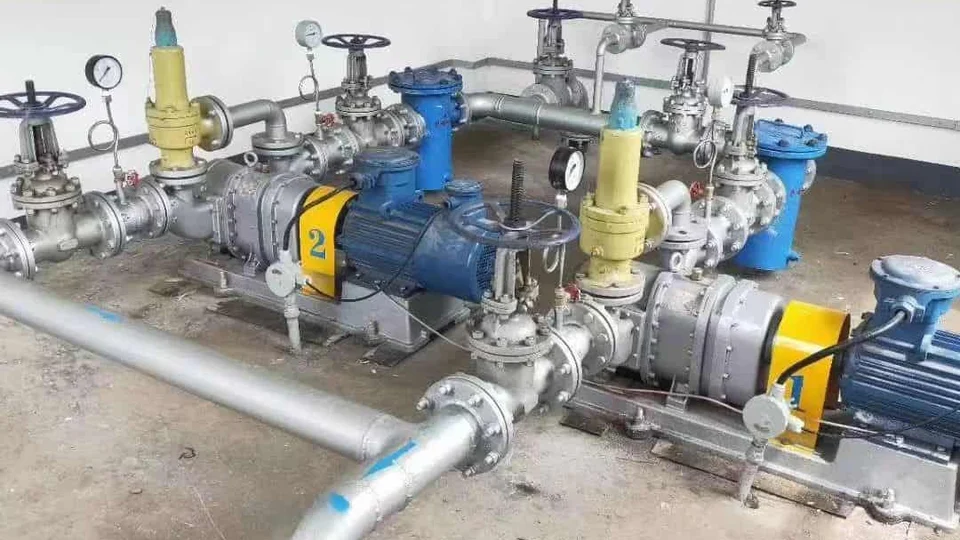
In pumping duty, the drive supplies shaft power to move liquid against a pressure difference. In hydraulic motor duty, the pressure-driven liquid supplies shaft torque instead. The shaft can then drive a generator through an arrangement selected for that operating range.
Ask the equipment supplier to confirm suitability in motor or generating duty: permissible pressure at both ports, speed and torque, shaft loading, seals, lubrication, and materials. Request efficiency data for this operating mode. A pump curve, a motor nameplate, or a statement that the pump can transfer liquid in both directions is insufficient for a generation proposal.
The pumping principle explains the displacement cycle. The reversible-flow guide concerns driven liquid transfer; reversing a drive is not a conversion procedure for a generating system.
3. What the Welsh Water and Vogelsang Examples Show
A supplier-authored report in Pumps & Systems describes a Welsh Water treatment installation with a gravity-fed raw-water supply. A rotary lobe machine and generator recovered energy while maintaining the outlet pressure needed to feed an elevated treatment tank. The report also describes flow control and provisions for a controlled shutdown during a grid interruption.
Read the original Renewable Power with Rotary Lobe Pumps report, co-authored by Vogelsang representative Marino Curati. It is an external project example, not a YANESS installation or a performance guarantee for another site.
Vogelsang also describes rotary lobe generators recovering hydraulic energy in its pump test benches. The recovered electricity feeds back into the test drive. This is energy recovery within a powered circuit, a different energy source from gravity-fed hydropower.
See Vogelsang THINK RED, edition 3, PDF page 14. In either case, ask for generating-duty data for the machine you are considering.
4. Estimate Hydraulic Power Before Electrical Output
For an incompressible liquid, hydraulic power available across the recovery machine is pressure drop multiplied by volumetric flow: P = Δp × Q. With Δp in bar and Q in m³/h, the result in kilowatts is P_hydraulic = Δp × Q ÷ 36. Use the pressure drop available across the machine, not the whole supply pressure.
For a head-based water calculation, P_hydraulic = ρ × g × Q × H, using density in kg/m³, Q in m³/s, H in metres, and g approximately 9.81 m/s²; the result is watts. H must be the net head across the machine. Where measuring sections differ in elevation or velocity, include those terms when establishing net head. Do not count pipe losses twice or mix metres of head with bar.
If project auxiliaries then consumed an assumed 0.20 kW, net output would be 3.80 kW. At that same net output for an assumed 4,000 operating hours, annual recovered energy would be 15,200 kWh. Real output changes with flow, pressure, efficiency, and downtime: calculate over the operating profile and separate on-site consumption from any permitted export.
5. Keep Water Delivery and Electrical Control in the Design
Energy recovery must fit the original water-delivery duty. Define the minimum downstream pressure and required flow, including periods when generation is unavailable. Have the system designer establish bypass or pressure-control arrangements, isolation, and the response to a blocked or stopped machine. Do not remove a pressure-reducing valve without a coordinated hydraulic design.
The electrical design must also address what happens when the generator loses its load or the grid disconnects. Ask how speed is limited, hydraulic transients are managed, and the system reaches a controlled shutdown or bypass state. Generator choice, regenerative power electronics, protection, and any grid connection need review for the proposed installation; a standard motor and VFD are not automatically a complete generating package.
Review liquid quality, abrasive solids, cavitation margin, seal conditions, and pressure limits at both ports. Include cleaning, maintenance access, and any drinking-water contact requirements where relevant. Compare the supported operating range and lifecycle costs with other suitable turbines or pressure-recovery devices before selecting a rotary lobe solution.
6. What to Send for a Project Review
Start with a marked-up flow diagram showing the water source, elevation changes, proposed recovery point, existing pressure-control valve, bypasses, and downstream destination. State whether the source is gravity-fed or pumped, and identify which flow and pressure readings were recorded together.
- Hydraulic profile: minimum, normal, and maximum flow; inlet and outlet pressures at the proposed machine; required downstream pressure; measurement locations; and operating hours or seasonal records.
- Liquid conditions: temperature, density, solids and grit, chemistry, and any water-quality or wetted-material requirements.
- Electrical destination: supply voltage and frequency, on-site loads, proposed generator or converter, and whether export is intended.
- Operating constraints: supply continuity, loss-of-load response, existing bypass/control arrangement, available space, and maintenance access.
Agree who is responsible for the machine, hydraulic controls, and electrical equipment before comparing proposals. Ask each supplier to state the operating range, expected output, and what is included in its scope.