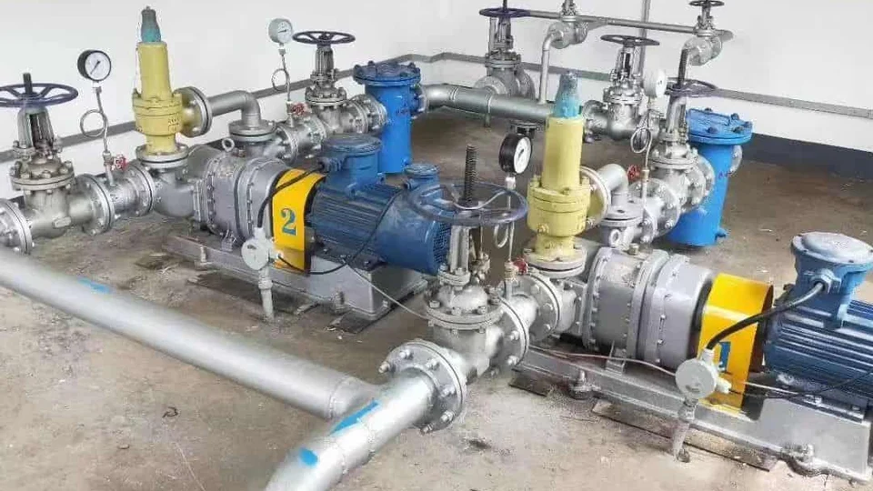
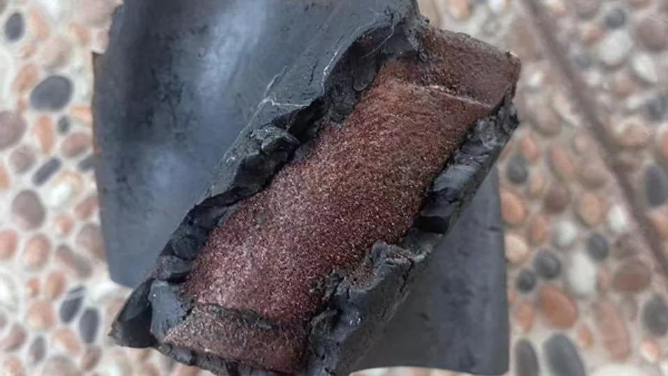
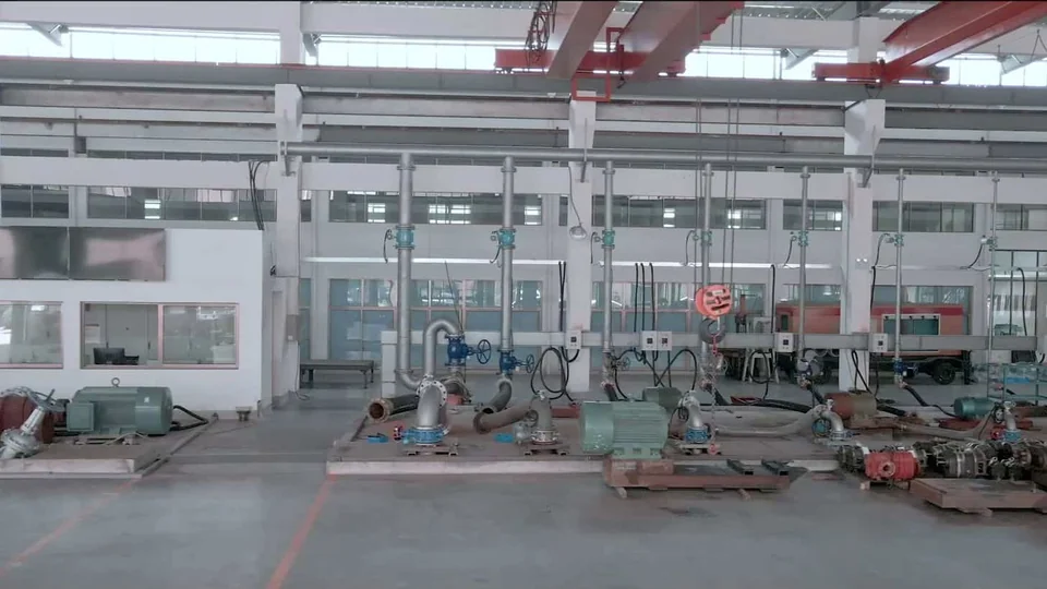
The names are easy to mix up. Open a drawing of a Roots blower and a rotary lobe pump, and you will see a similar pair of timed rotors. But a blower on an aeration line and a pump on a sludge line are doing different work. You would not replace one with the other.
Ask what passes through the machine: air, another gas, or liquid? That answer is more useful than the rotor shape. Here, “rotary lobe pump” means the liquid-transfer equipment; “Roots pump” can also refer to vacuum equipment, which we cover below.
| What the process needs | Equipment route to investigate |
|---|---|
| Supply air or gas | A blower or compressor selected for the gas, flow conditions, and required pressure difference. |
| Transfer a liquid or slurry | A liquid pump selected for viscosity, solids, suction conditions, flow, and differential pressure. |
| Remove gas to create a vacuum | A vacuum system; a Roots vacuum booster may be one part of it, depending on the required operating range. |
| Transfer liquid with intermittent air entry | Review the liquid pump and its operating limits. Occasional air handling does not establish a continuous blower duty. |
Equipment names and rotor appearance are starting clues. Confirm the handled medium and documented duty before choosing a machine.
1. First, Check What Goes Through the Machine
A Roots blower handles air or gas. It may supply air to wastewater aeration diffusers or provide gas for pneumatic conveying. Even in a water-treatment plant, the blower is moving gas, not the wastewater.
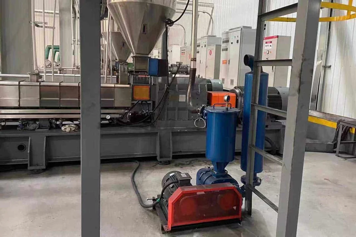
A liquid-transfer rotary lobe pump moves liquids and suitable slurries. The fluid contacts its casing, rotors and seals, so materials and clearances have to suit the liquid, temperature and solids. That is a different selection from an air blower.
For a gas-equipment reference, see Busch’s rotary lobe blower overview. For the liquid-transfer equipment discussed on this site, start with the YANESS rotary lobe pump guide.
2. Similar Rotors, Different Machines
Both use timed shafts turning in opposite directions. Spaces between the rotors and housing carry the medium from inlet to outlet. That shared displacement principle explains the familiar cross-section.
Lobe count alone will not identify the duty. Check the model documentation for the medium, seals, materials, operating speed, and pressure and temperature limits. A similar rotor outline does not mean the complete machines can be exchanged.
The liquid-pump working principle illustrates the displacement cycle. The rotor profile guide explains how the liquid-pump rotor choice affects passage and flow behavior.
3. Compare the Right Performance Data
For gas, give the composition, inlet temperature and absolute pressure, outlet pressure, and flow basis. Normal or standard m³/h refers to stated reference conditions. It is not automatically the same as actual m³/h at the inlet. Compression and the resulting gas temperature also affect selection.
For liquid, give the flow, suction and discharge conditions, solids, and viscosity at both startup and operating temperatures. Internal slip and incomplete inlet filling can reduce delivered flow below theoretical displacement.
Use model-specific performance data. Motor kW alone does not establish the usable pressure range, and a general “blower versus pump” pressure or price comparison tells you little when the machines handle different media.
4. Two Jobs in the Same Treatment Plant
A wastewater plant makes the distinction clear. The blower supplies air to submerged diffusers. On a separate line, a liquid pump transfers sludge between tanks or to the next treatment stage. The plant may need both machines.
Pneumatic conveying creates a similar naming trap. The blower supplies the conveying gas; its rotor chamber is not automatically intended to pass the bulk solid being conveyed. Tell the supplier whether dust, moisture, liquid carryover, or other contaminants can reach the gas-handling machine and confirm the required separation or protection.
If your actual duty is sludge or wastewater transfer, explore liquid-pump applications in wastewater treatment. For aeration-air equipment, prepare a gas-duty specification for a blower supplier.
5. Roots Pumps, Self-Priming and Dry Running
In vacuum engineering, “Roots pump” refers to gas-handling equipment. A Roots vacuum booster is often paired with a backing pump. Check the system arrangement and operating range; the word “pump” does not mean it is intended for liquid transfer.
Leybold’s explanation of a Roots vacuum pump describes this vacuum-system use of the term.
A liquid pump may handle air while priming or emptying a tank, but that does not establish continuous gas-handling duty. Its permitted dry-running exposure depends on the pump, seal support, speed, duration and monitoring.
On a blower, “dry” or “oil-free” may describe the gas path. Gears and bearings can still have their own lubrication requirements. Follow the model’s maintenance instructions.
For liquid pumping, review the separate guides to dry-run capability and self-priming conditions.
6. What to Send With Your Inquiry
Start with the job in plain words: “supply aeration air,” “evacuate this vessel,” or “transfer this sludge.” Add a process sketch showing the source, destination and pressure measurement points, then include the relevant data below.
- For air or gas: identify the composition, inlet temperature and absolute pressure, required outlet pressure or vacuum, flow and its reference conditions, operating pattern, and possible contamination.
- For liquid: identify the fluid, viscosity and temperature, solids, required flow and differential pressure, inlet arrangement, and startup/shutdown conditions.
- For a replacement: include the existing manufacturer, model, nameplate, connected equipment, and the reason for replacement. Keep gas and liquid duties separate if both appear in the project.
For liquid transfer, send YANESS the fluid and operating data for a pump review. For aeration, gas compression or vacuum generation, take the gas-duty specification to a supplier of that equipment.