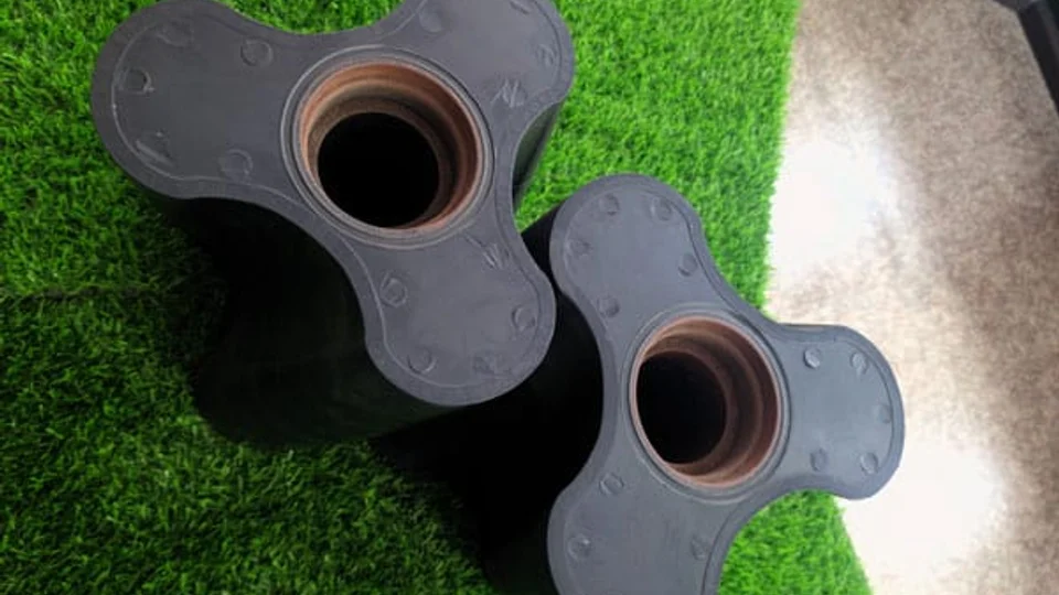
The curved flanks of a helical rotor can be awkward to reach with a tool held in one direction. Five-axis milling gives the process planner more options for approaching those surfaces. That is the practical reason to consider it.
For the pump buyer, the next questions concern the part that comes off the machine: does the profile match the drawing, does the rotor locate correctly on its shaft, and are the assembled clearances right for the duty? A machining description should lead to those checks.
| Feature | Why it matters to the pump |
|---|---|
| Rotor contour | The finished profile must match the drawing and work with its paired rotor throughout rotation. |
| Mounting and location | The bore and other locating features establish the rotor position on the shaft and affect the assembled relationship. |
| Running clearances | Rotor-to-rotor, radial, and axial gaps must suit the model, material, pressure, and temperature conditions. |
| Finish and inspection | Check the specified surfaces after final finishing, together with dimensional results and part identification. |
Review the machining plan, finished-part measurements and assembled-pump checks as separate records.
1. What Five-Axis Machining Means
Five-axis milling combines three linear axes with two rotary axes. The rotary movement can come from the table, the tool head, or both, changing the tool’s orientation relative to the workpiece.
- 3+2 machining: the tool is positioned at an angle, then cuts a region with that orientation fixed.
- Simultaneous five-axis machining: the tool orientation can change as it follows the cutting path.
A rotor may use both strategies. Siemens’ comparison of 3+2 and five-axis milling illustrates the distinction.
2. Where the Extra Tool Access Helps
Tilting the tool or workpiece can help reach a curved flank without extending a long cutter past adjacent features. Where the geometry allows, it can also reduce re-clamping. Tool choice, fixture stiffness and setup still need to suit the material and rotor design.
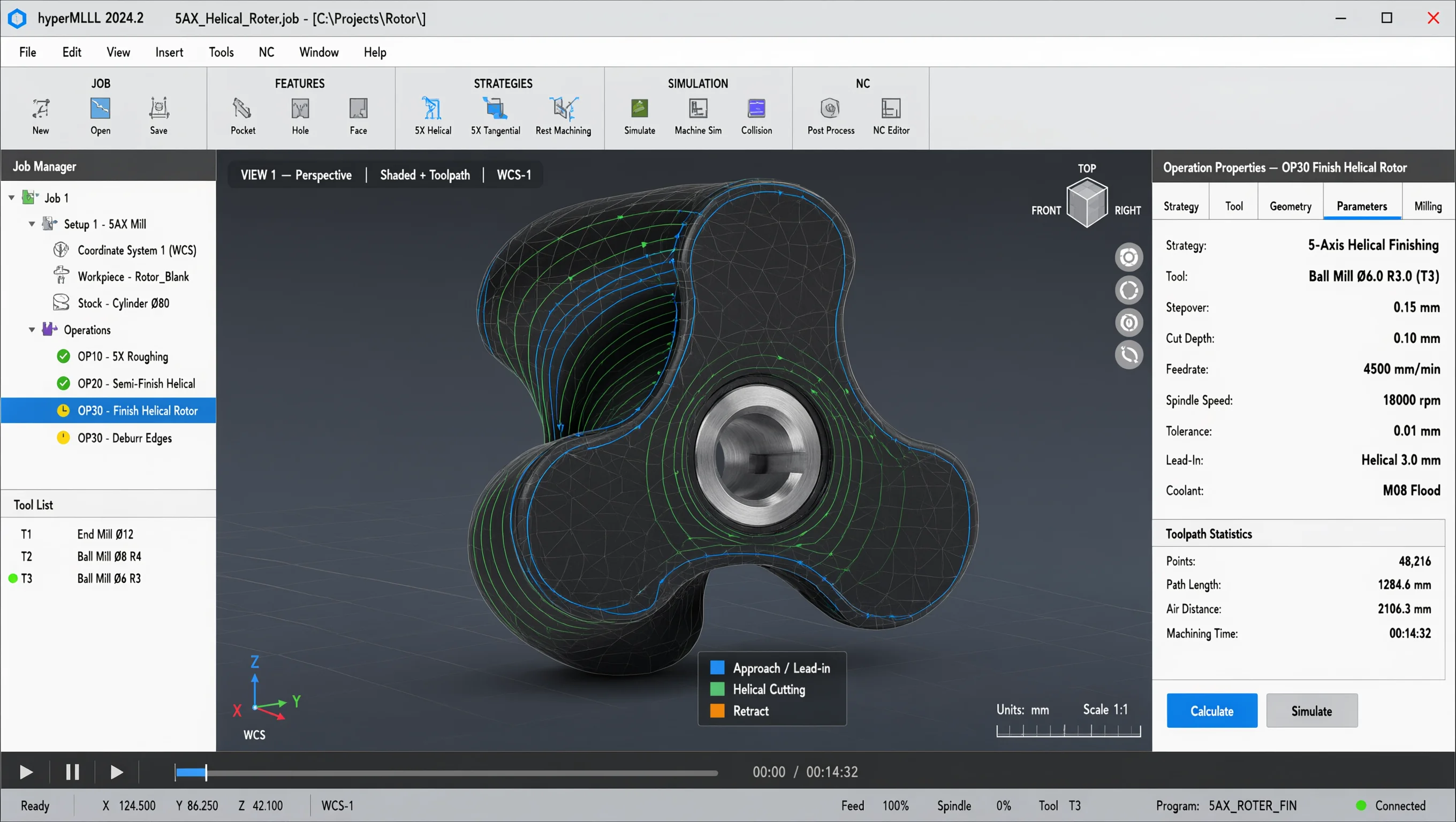
A simpler rotor profile may be made effectively by another machining route. Choose the process around the drawing requirements and tool access rather than adding axes for their own sake.
For the general tool-access principle, see Siemens’ five-axis CAM explanation. More workshop and CAM imagery is available in the YANESS manufacturing overview.
3. From the CAD Profile to a Finished Rotor
A useful manufacturing review follows four stages. The exact operations depend on the rotor drawing, material and machine:
- Agree the part: drawing and CAD revision, material, reference datums, locating features and surface requirements.
- Plan the cut: stock, fixtures, toolpaths and a machine-compatible program. Review tool access and potential interference in CAM.
- Machine and finish: roughing, finishing and any separate bore or fastening operations. Plan heat treatment, if specified, and any final machining allowance.
- Inspect the supplied condition: check the profile and locating features after deburring, polishing or other specified finishing.
The bore, key or other locating feature establishes how the rotor sits on the shaft. Include it in the inspection plan along with the visible lobe contour.
4. Check the Rotor in the Assembled Pump
In a non-contacting liquid lobe pump, the rotor dimensions work together with the shafts, timing, casing and cover. Check three distinct gaps in the assembled pump:
- Rotor-to-rotor: the gap between the paired profiles as they rotate.
- Radial: the gap between the rotor perimeter and the casing.
- Axial: the end gaps between the rotors and the pumphead faces.
Use the model-specific limits and inspection positions. Clearance must allow for temperature changes and loading while controlling internal slip; the smallest possible gap is not the target for every duty. Check the locating surfaces, shaft condition and timing as well as the rotor itself.
See the working-principle guide for timing and running clearances, and the structural-design guide for shaft support. As an external example of model-specific information, the Alfa Laval SX manual lists separate pumphead clearances. Those values are not YANESS assembly instructions.
5. Choose Material and Profile for the Duty
Select the rotor material against the liquid, solids, temperature and cleaning exposure, together with the rest of the wet end. “Five-axis machined” does not specify an alloy or establish its chemical compatibility.
Then review the profile: bi-lobe, straight tri-lobe or helical tri-lobe. Discuss solids passage, pulsation, speed, inlet filling and product handling for the proposed configuration. Material, profile and manufacturing route are related decisions, but one does not settle the others.
Use the materials and compatibility guide and rotor-profile guide for those choices. For clean-process projects, also review the complete sanitary pump configuration, including seals, connections, finish, and cleaning requirements.
6. Agree the Inspection Records Before Production
Agree the critical features, inspection methods and acceptance limits before production. Tie the results to the drawing revision and supplied part or batch. Include any required material documentation in the order.
- Geometry: specified contour dimensions and locating features, together with the relevant datums and any runout requirements.
- Final surface condition: the surfaces to be assessed, the finish parameter and acceptance limit where specified, and the condition after polishing or other finishing.
- Assembly: paired-rotor identification where applicable, timing and clearance checks, and the procedure for the particular pump configuration.
- Package testing: any agreed running, leakage, or performance checks, with the test conditions and scope recorded.
Component measurements and an assembled-pump test answer different questions. Ask for the evidence that matches each acceptance requirement. For clean-process duties, review the complete product-contact geometry and cleaning conditions as well as the surface finish.
7. What to Send With Your Inquiry
- OEM rotor: drawing and available CAD model, revision, material, quantity, critical dimensions, surface requirements and inspection expectations. Flag features still under review.
- Replacement rotor: pump model and serial number, rotor markings, existing material and reason for replacement. Include photos, but confirm the match to the shafts, casing, timing and paired rotor.
- Complete pump: flow, differential pressure, viscosity at startup and operating temperature, solids and cleaning conditions.